Name/Title
Drawings, ArchitecturalEntry/Object ID
2024.1.06Description
Architectural drawings by Charles Howard Kable, Architect: Residence for Mr. & Mrs. Walter T. Smith, P.O. Aurora, OR/Ph. Newburg 3F5. c. 1945-46.
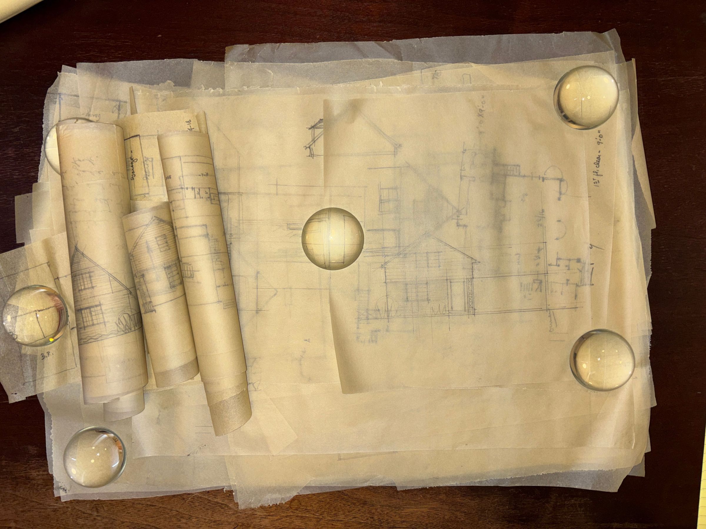
PROCESS SKETCHES & NOTES:
Sketches on yellow trace/vellum. Notes on sketchpad/legal pad. Most entries undated. Dimensions vary from 4.5" x 10" to 16" x 22".
A - Terrace sketch (No Date)
B - Elevation sketch (No Date)
C - Elevation sketch (No Date)
D - Gable and room sketch study (No Date)
E - Plan sketch (No Date)
F - Plan sketch (No Date)
G - Plan sketch (03/02/46)
H - Elevation sketch (No Date)
I - Roof sketch (No Date)
J - Plan sketch (No Date)
K - Plan sketch (No Date)
L - Plan sketch (No Date)
M - Plan sketch (No Date)
N - Plan sketch, 1st Floor, Scheme A (04/x18/45)
O - Plan sketch - Den (No Date)
P - Elevation sketch (No Date)
Q - Plan sketch (No Date)
R - Plan sketch, Scheme 5 (5/17/45)
S - Plan sketch (No Date)
T - Plan sketch & notes (12/28/45)
U - Elevation sketch (No Date)
V - Elevation sketch (No Date)
W - Plan sketch (04/18/[45])
X - Plan Sketch "C" (04/18/[45])
Y - Plan sketch "#5" (No Date)
Z - Pan sketch "#2" (No Date)
AA - Plan sketch "Scheme #2" (04/13/45)
AB - Plan sketch (No Date)
AC - Plan sketch (No Date)
AD - Elevation sketch (No Date)
AE - Elevation sketch (No Date)
AF - Plan sketch (04/18/45)
AG - Plan sketch (No Date)
AH - Elevation sketch (No Date)
AI - Plan sketch (04/18/45)
AJ - Sketch "1st FL - Tower plan" (No Date)
AK - Sketch "2nd FL - Tower plan" (No Date)
AL - Plan sketch (No Date)
AM - Elevation sketch "32/27", "6" (No Date)
AN - Plan studies sketch (No Date)
AO - Plan sketch "Plan by EMK" (05/25/45)
AP - Plan sketch "THIS" (05/15/45)
AQ - Plan sketch "Used as Scheme #1" (04/13/45)
AR - Notes, "Principal Changes" (11/02/45)
AS - Plan sketch (No Date)
AT - Window sketch (No Date)
AU - Notes with attached sketches (03/19/46)
AV - Notes with attached sketch (10/06/45)
AW - Notes/sketch (No Date)
AX - Entrance scheme - Notes/sketches - "Address 5118 SE 52nd Ave"
AY - Framing detail sketch (No Date)
AZ - Notes (02/18/46)
SCALE PROCESS DRAWINGS:
Scale drawings on yellow trace. Dimensions vary up to 18" x 43".
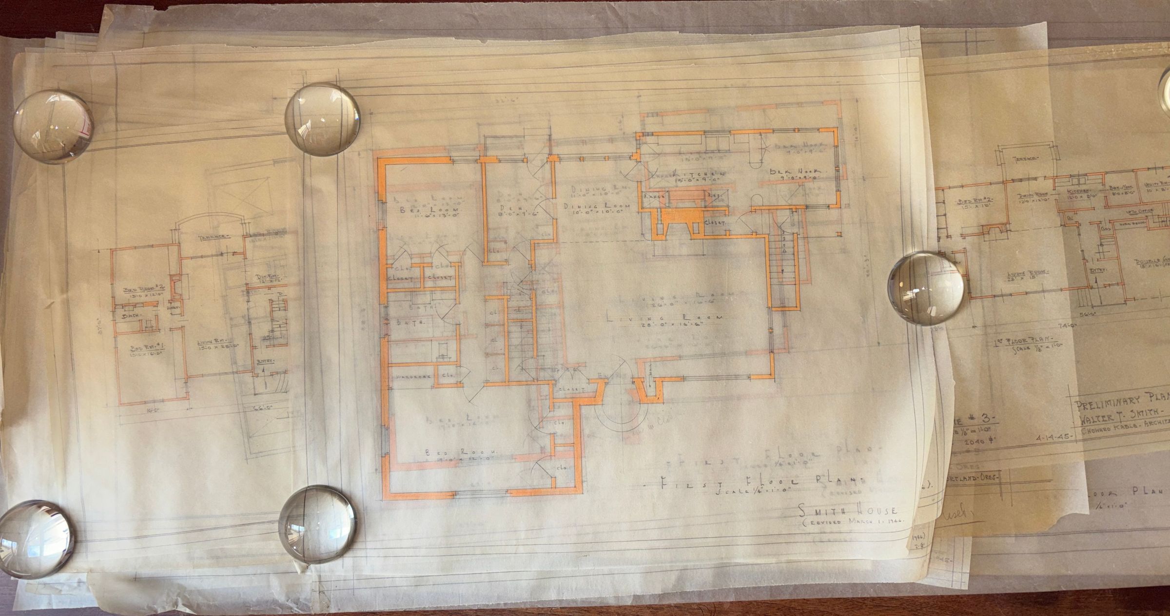
BA - Preliminary Plan - Scheme #1 (04/12/45)
BB - Preliminary Plans - Schemes #1-2-3 (04/14/45)
BC - Preliminary Plans - Scheme #5 (04/23/45)
BD - Plan drawing - Scheme #2 - Revised 1st Floor (04/24/45)
BE - Plan drawing - Scheme #4 (04/24/45)
BF - Sketch Elev. (Schem #2 Revised) (04/24/45)
BG - Plan/Elevation - Scheme #5 (05/17/45)
BH - Plan/Elevation - Scheme #6 (07/05/45)
BI - Plan/Elevation - Scheme #7 (09/15/45)
BJ - Sheet 4 - First Floor Plan, Second Floor Plan (09/17/45)
BK - Front Section Plan - Scheme #8 (09/22/45)
BL - Front Section Plan - Scheme #9 (09/25/45)
BM - Front Section Plan - Scheme #9 (09/25/45)
BN - Front Section Plan - Scheme #10 (09/25/45)
BO - First Floor Plan (10/17/45)
BP - West Elevation (10/17/45)
BQ - Front Elevation (10/17/45)
BR - Kitchen Details (10/17/45)
BS - Rear Elevation (10/17/45)
BT - East Elevation (10/17/45)
BU - First Floor Plan (11/26/45)
BV - First Floor Plan (03/01/46)
BW - First Floor Plan (03/06/46)
BX - West Elevation (03/11/46)
BY - Front Elevation (03/11/46)
BZ - Rear Elevation (03/11/46)
CA - West Elevation (03/22/46)
CB - First Floor Plan (03/15/46)
CC - Sheet 16/18 - Second Floor Plan (No Date)
CD - First Floor Plan (03/22/46)
CE - Second Floor Plan (03/22/46)
CF - Front Elevation (03/22/46)
CG - First Floor Plan (12/20/46)
CH - 1st Floor Plan, 2nd Floor Plan (No Date)
BLUEPRINT COPIES:
Various scale drawings on blueprint paper. Dimensions vary up to 16" x 38.5".
CI - (No Sheet #) - Scheme #5 - 1st Floor Plan, 2nd Floor Plan, Front Elevation (05/17/45)
CJ - (No Sheet #) - Scheme #6 - 1st Floor Plan, 2nd Floor Plan, Front Elevation (07/05/45)
CK - (No Sheet #) - Scheme #7 - First Floor Plan, Second Floor Plan, Front Elevation (09/12/45)
CL - (No Sheet #) - First Floor Plan [Torn fragment] (No Date)
CM - (No Sheet #) - First Floor Plan, Second Floor Plan (09/17/45)
CN - (No Sheet #) - First Floor Plan (03/15/46)
CO - (No Sheet #) - First Floor Plan (03/22/46)
CP - (No Sheet #) - Second Floor Plan (03/22/46)
CQ - (No Sheet #) - Front Elevation (03/22/46)
CR - (No Sheet #) - Rear Elevation (03/11/46)
CS - (No Sheet #) - West Elevation (03/22/46)
CONSTRUCTION DRAWINGS:
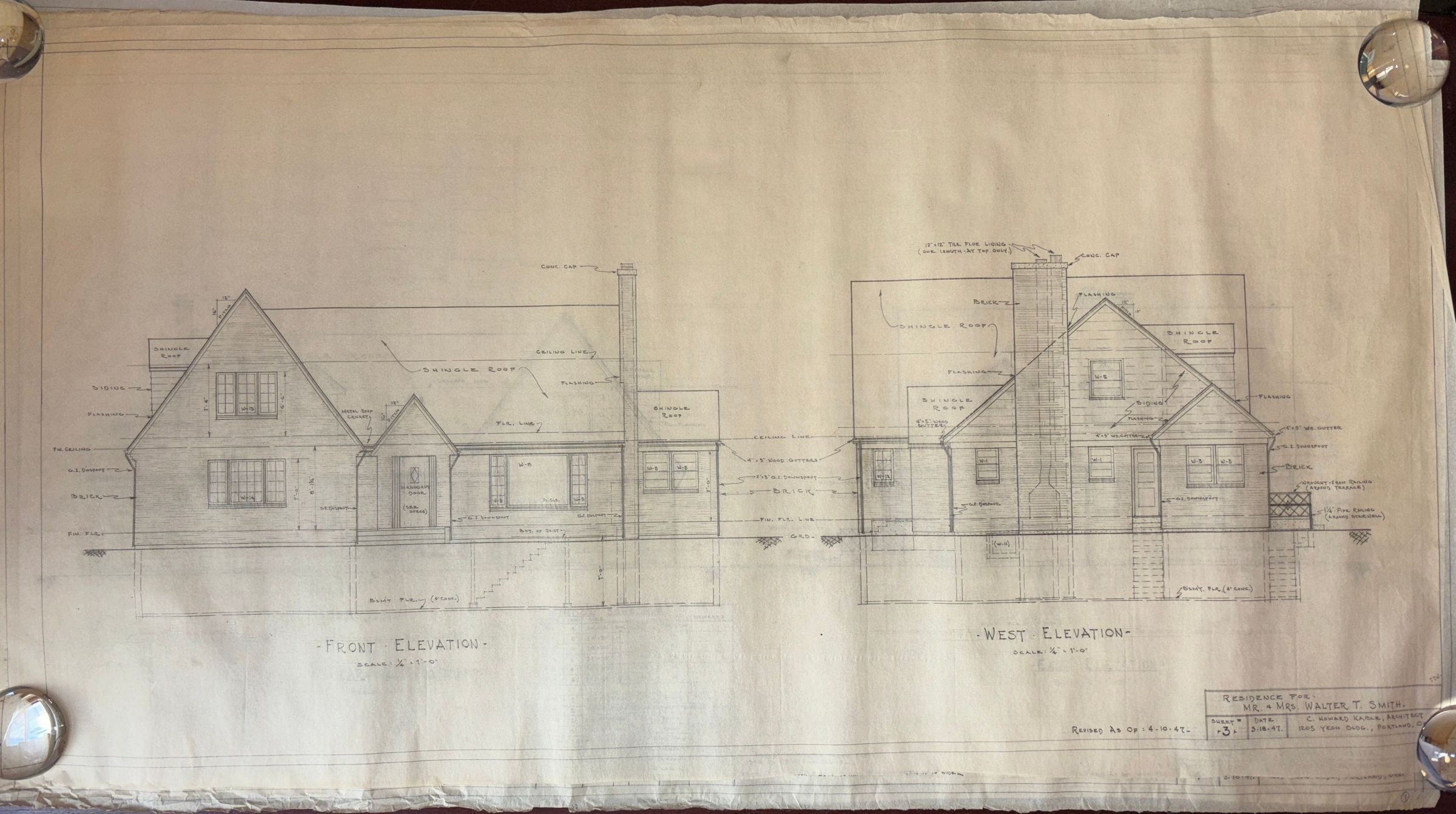
Scale construction drawings on yellow trace, mechanical drawing on white vellum. Dimensions 20" x 37".
CT - Sheet 1 - 1st Floor Plan, Basement Plan (03/18/47, rev. 04/10/47)
CU - Sheet 2 - 2nd Floor Plan, Details, Room Finish Schedule (04/18/47, rev. 04/10/47)
CV - Sheet 3 - Front Elevation, West Elevation (03/18/47)
CW - Sheet 3 - Front Elevation, West Elevation (03/18/47, rev. 04/10/47)
CX - Sheet 4 - Rear Elevation, East Elevation (03/18/47, rev. 04/10/47)
CY - Sheet 5 - Kitchen Details, Window Details (03/18/47, rev. 04/10/47)
CZ - Sheet 6 - Fireplace Details, Dining Room Cabinet Detail, Rear Entry Detail (04/18/47, rev. 04/10/47)
DA - Sheet 7 - Miscellaneous Details (03/18/47, rev. 04/10/47)
DB - Sheet H-1 - Forced Hot Water Heating System (W. Bruce Morrison, Mechanical Engineer) (06/17/47)Lexicon
Search Terms
Charles Howard Kable, C. Howard Kable, Residence, Walter T. Smith, Aurora, OR, Smith House