Name/Title
Maps of Great Western Reservoir 1904Entry/Object ID
2023.16.1.a-dScope and Content
Maps of Great Western Reservoir 1904
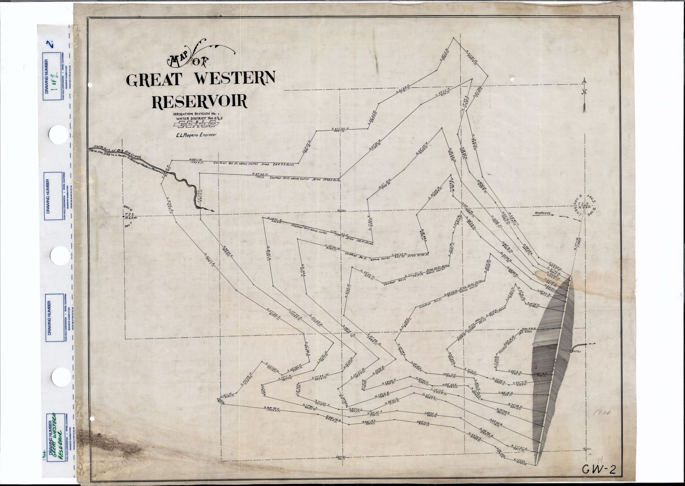
a. The first map (pictured) reads "Map of the Great Western Reservoir" in the top left portion. Beneath this, it states that the content of this map is within Irrigation Division No. 1 and Water Division Nos. 6 and 2. The scale of the map is 200 feet to each inch, and E.L. Rogers was the map's engineer. The map mainly consists of a series of lines that mark the area around a dam (which is the white area between the shaded sections of the map, which are most likely indicating downward slopes). Each line is marked with geographical coordinates. Beneath each set of coordinates, there is a measurement in feet, which is most likely the elevation of the land along that line based on the known elevation of a given point (which is currently unknown). Beneath some of these lines, contour distance from the outlet, which is most likely the point labeled "Outlet" on the east side of the dam, is present. Other notable features of this map include the Wasteway with arrows pointing east, and the Outlet on the right of the sloped areas, which is also pointing towards the east. The north fork of Big Dry Creek is feeding into the area from the west. Below this creek, it marks the McKay Ditch feeding into the Great Western Reservoir. The map is also split up into numbered sections by dotted lines.
b. The second map is another map of the Great Western Reservoir. The engineer of this map is also E.L. Rogers, and the scale is the same: each inch is equivalent to 200 feet. On this map, however, the land is only part of Water Division No. 2 instead of Nos. 2 and 6. On the left hand side of the map, there is a section titled "Statement of Claim to Water Right." This section discusses A.J. Zang's claim to water from the Big Dry Creek, which he would use to fill the Great Western Reservoir. He lays out the estimated costs and measurements that will be needed in order to fill the Reservoir. There is also a chart that shows the estimated capacities (in cubic feet) and surface areas (to the nearest foot) of water in various sections of the Great Western Reservoir once they were filled. The whole statement is signed by A.J. Zang, E.L. Rogers, and Nathan P. Sanders, all of whom certify that the map and claim are valid. Beneath this, the State Engineer, L.J. Garpeuter, also signed the map, stating that A.J. Zang's claim was approved by the State of Colorado. The rest of the map looks very similar to the first map, with the addition of a Well Tower at the western base of the dam, the names of the owners of different sections of land written over their respective properties, the northernmost part of the dam marked as the "Initial Point of Survey," and a larger Spillway replacing the Wasteway. The property owners mentioned on the map are E. Rich, W.H. Whitehead, and A.J. Zang.
c. The third map is a "Plat Showing [the] Location of Service or Distributing Ditch from The Great Western Reservoir." This map is also split into numbered sections by dotted lines. This map is by Peter O'Brian, and the scale is 500 feet to each inch. On the very left of the map, the dam is marked by a white line and shaded area. From the east end of the dam, two lines extend towards the east. Both of these lines are sectioned and reach towards the same point on the right of the map, but the sections of the dotted line are marked with coordinates and cover a shorter distance than those of the solid line. Thick white lines, which are most likely roads, are also present on the map. Measurements from the ditch are also present near the bottom right corner, including information about the depth, width, length, slope, grade, and carrying capacity of the area. Several names are also present on various areas of the map, which most likely indicates that these people owned land in the marked areas. The names are A.J. Zang, Peter Magnes, G.H. Church, F.M. Miller, F.J. Hecht, E.D. Henry, F.T. Henry, F.F. Henry, and Campbell. This map was much less detailed than the first two maps and contained lots of empty space.
d. The fourth map is extremely similar to the third map: the two lines marked with coordinates are exactly the same on both maps. There is also a section with ditch measurements in the bottom right of this map, which contains the same information as the previous map. Like the previous map, this map shows the location of the distributing ditch from the Great Western Reservoir. However, the center line of the dam is labeled more clearly than on the third map, and the area around the dam is not shaded. Instead, its borders are marked with solid lines. Very thin pencil lines are visible on this map, which mark different areas and coordinates, filling in some of the empty space on the map. An unnamed road is drawn near the top right of the map, and some unlabeled drawings probably indicate either the geography or elevation of the marked areas. Some names of property owners, including Rozenbaum, Miller, and Church, are also written in pencil on different sections of the map.Collection
Permanent CollectionLexicon
Nomenclature 4.0
Nomenclature Tertiary Object Term
Survey, LandNomenclature Secondary Object Term
MapNomenclature Primary Object Term
CartographNomenclature Sub-Class
Graphic DocumentsNomenclature Class
Documentary ObjectsNomenclature Category
Category 08: Communication ObjectsRelationships
Related Person or Organization
Person or Organization
E.L. Rogers, Adolph Joseph Zang, E. Rich, Nathan P. Sanders, George Henry Church, W.H. Whitehead, Peter Magnes, F.J. Hecht, F.M. Miller, E.D. Henry, F.F. Henry, F.T. HenryRelated Places
Place
* Untyped Place
Great Western ReservoirLocation
Broomfield, CO