Name/Title
Print, PhotographicEntry/Object ID
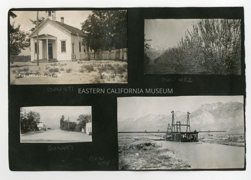
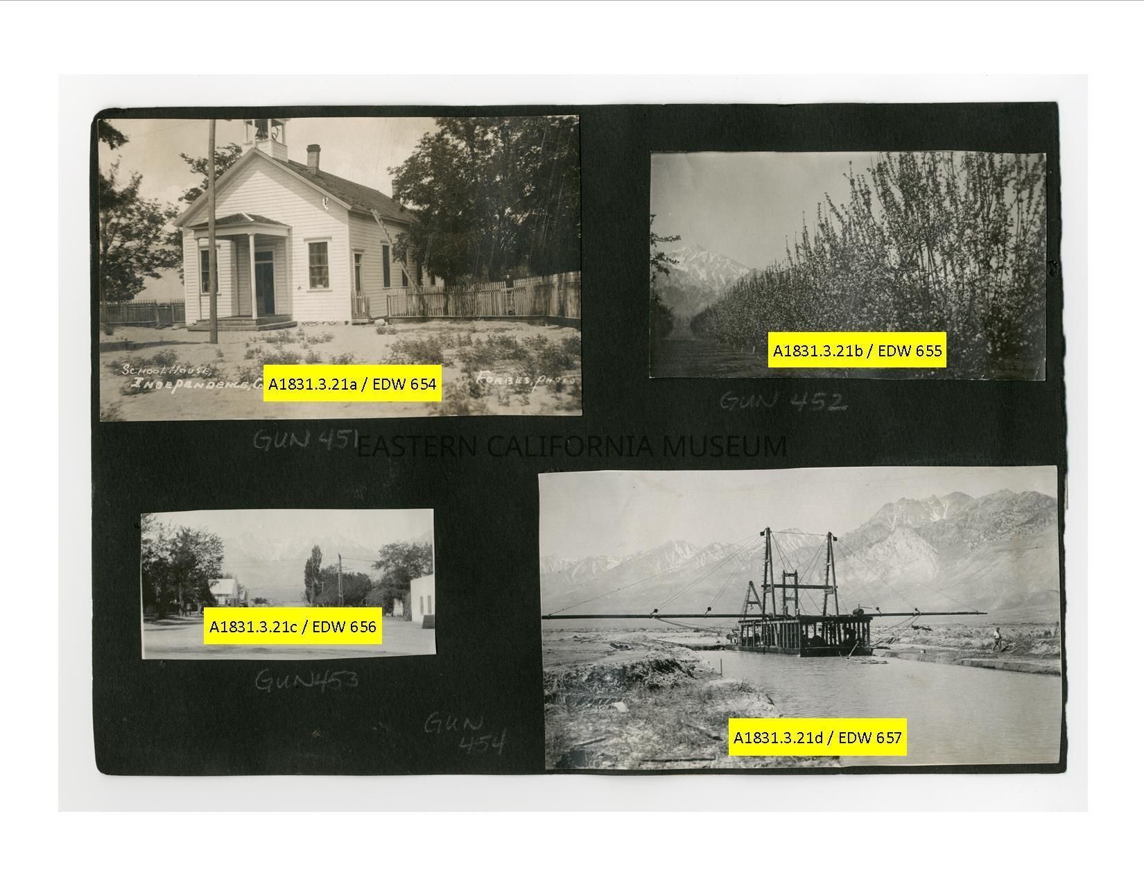
A1831.3.21a-dDescription
A1831.3.21a: A. A. Forbes photo titled, "School House, Independence, Cal." and given his ID #1089. It has a bell tower.
A1831.3.21b: Photo of a blossoming orchard with the Sierra Nevada in the background. Location may be Manzanar and Mt. Williamson.
A1831.3.21c: Photo of a street scene looking west towards the Sierra Nevada. Not sure which town it is--maybe Independence.
A1831.3.21d: Photo of a dredge during the constructin of the Los Angeles aqueduct (c. 1908-1913). Sierra Nevada mountain range in back. Information compiled by R. Potashin from the LA Aqueduct Construction Annual Report, 1908:
DWP Suction Dredge constructing channel for the LA Aqueduct, location between the Intake and Black Rock Spring. This is the Open, Unlined section of the aqueduct, whose construction falls under the Owens Valley Division of the project. Note aqueduct laborer in front of dredge. Mr. Roderick Mackay master mechanic engineer of the Los Angeles Aqueduct developed the electrically operated suction dredges employed and supervised their installation.
The diversion conduit may be considered as a new channel of the Owens River located in a more favorable position for controlling the stream flow and conveying the water to its new destination. The conduit is also favorably located to receive the waters of the tributary mountain streams from Division Creek to Walker Creek.
The first twenty one miles is being excavated by means of a hydraulic dredge The motive power is 110 KW or 147 J4 HP required is furnished by the City's hydroelectric power plant No 1 situated on Division Creek A second dredge heavier and of somewhat larger capacity than the first is being constructed and will be placed in operation south of Independence From the rate of progress made by Dredge No 1 it is estimated that each dredge will make an average progress of 3-4 miles per year or that three years will be the total time required to complete the 21 miles.
The suction dredges are both practically same in design and construction They have steel hull 55 ft. long 20.5 ft. beam and 6 ft. deep which is divided by transverse bulkheads four compartments A 12 in Eclipse horizontal shaft side suction centrifugal sand and pump built by the United Iron Works of Oakland Cal is installed on each hull for dredging These pumps were designed specially for work each of them having a very heavy cast shell instead of containing the usual liners The pump is located 15 ft. from the end of the hull with its shaft coinciding with longitudinal center line of the latter With arrangement an entirely straight suction line extending to a ladder at the forward end of hull is secured The pump is driven by a 75 continuous speed three phase 60 cycle 2300 Westinghouse motor to which it is connected a Morse rocker joint silent chain The line of the dredge pump is joined at the end of the hull by means of a coupling to flexible suction hose carried by a steel A frame ladder hinged on a shoe on the hull The ladder also carries a cutter used to loosen the materials so they will into the suction of the pump readily.Collection
Helen Gunn Edwards Collection