Name/Title
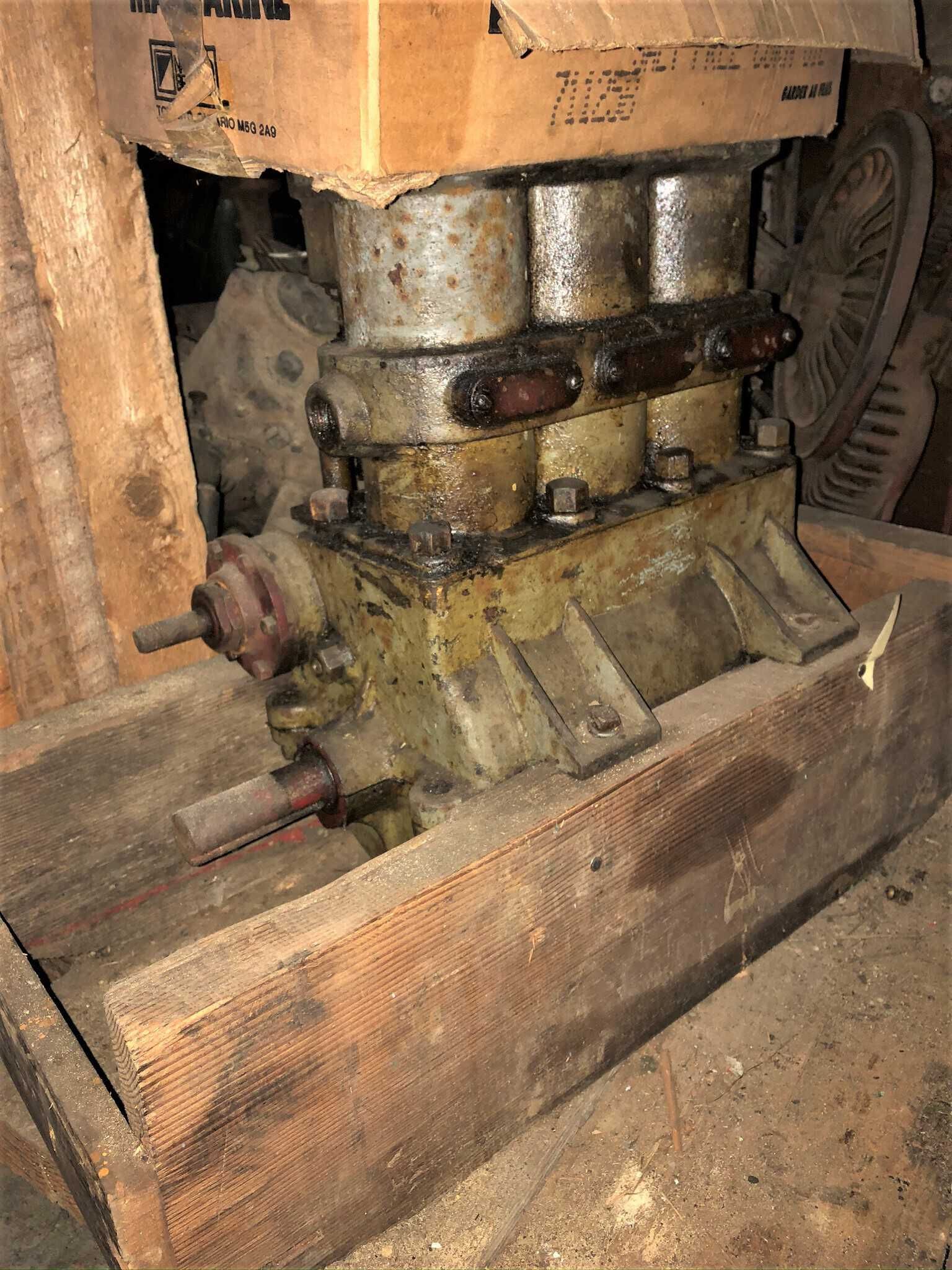
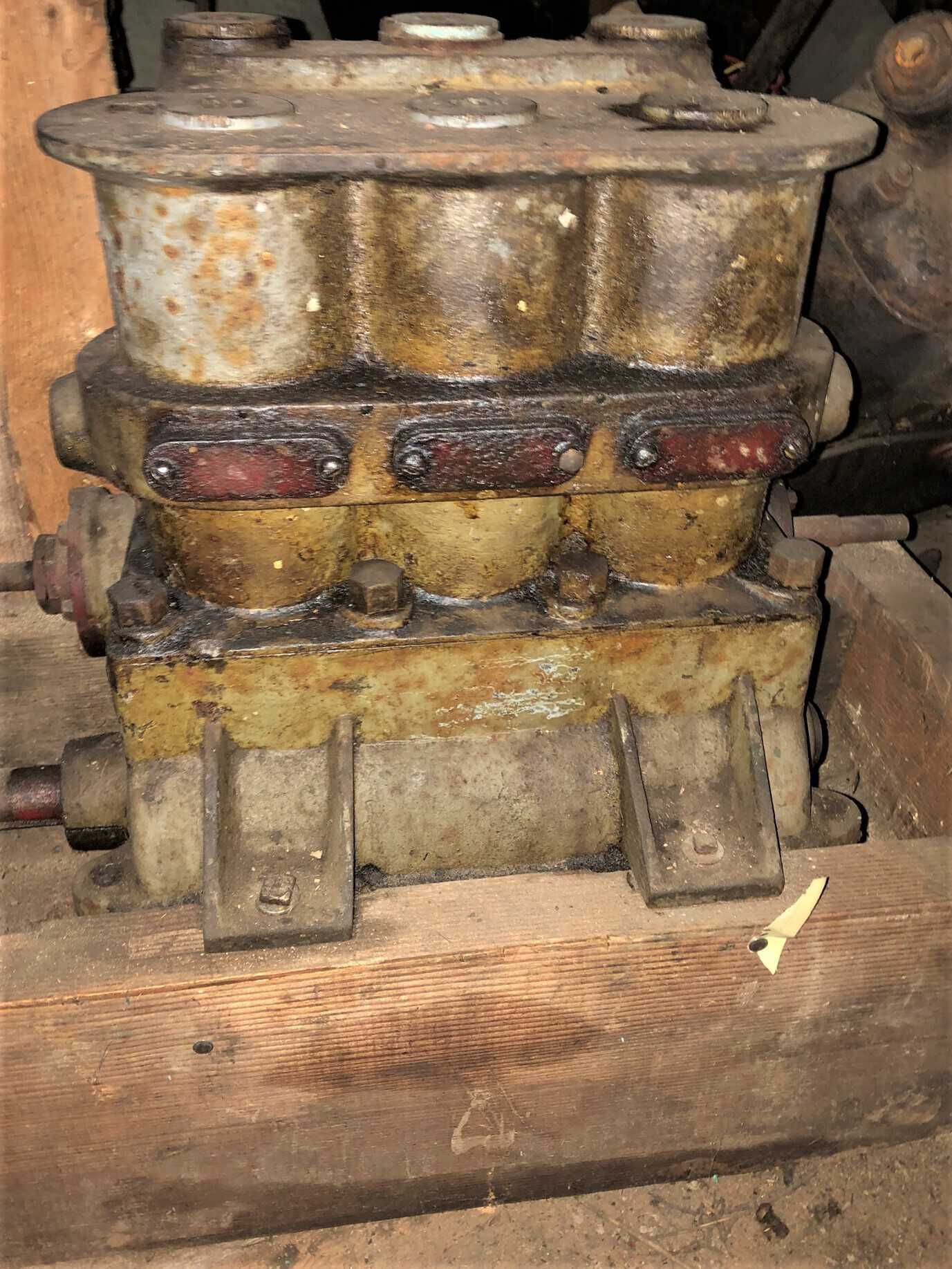
Engine - Deiter twin cylinder uniflow marine, unrestoredDescription
Deiter twin cylinder uniflow marine steam engine, unrestored. From Stan MacIntyre. Possibly off a Kooteney lake fast launch vessel.
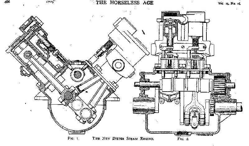
The New Dieter Steam Engine
The following illustration and description of the Dieter engine appeared in THE HORSELESS AGE vol. 15 #16, 1905, p. 446. This description pertains to a 4-cylinder version of the engine, with slightly smaller bore and stroke than the 3-cylinder version, but the mechanical construction is very similar to the engine described above.
The Dieter engine, manufactured by the Dieter Steam Engine Company of 106 Liberty Street, New York City, is a four cylinder, single acting steam motor constructed closely upon gas engine lines. Fig. 1 is a view looking along the crank shaft, with one cylinder shown in section, and Fig. 2 is a section through two cylinders in the crank shaft axis. The motor consists of two pairs of cylinders, the individual members of each pair having their axes inclined at right angles, and their connecting rods acting upon the same crank of the two-throw crank shaft. The two cylinders, which have the same angular relation to the crank shaft, are cast integral, and thus two castings suffice for all four cylinders. The crank case is split in a horizontal plane along the axis of the crank shaft, the cylinder castings being bolted to the upper section. As each cylinder is developing power during each down stroke, and as the two cranks are set at 180o apart, two cylinders (one of each pair) are always doing work. Trunk pistons are used, exactly as employed in gas engines, and these are packed by three expanding metal rings above, and one below the wrist pin. H-section connecting rods are made use of, and as the two rods of each cylinder pair must be attached to a common crank pin one connecting rod tip is made forked, and the tip of the other rod occupies the portion of the pin between the fork of the other. This is plainly shown in Fig. 2. The bore of these cylinders is 2.5 inches, and the stroke 3.5 inches, and the engine is stated to develop 13 horse power at 600 revolutions per minute, with 250 pounds boiler pressure, and to be able to run at 1,200 revolutions per minute safely with a nearly corresponding increase of output. In this engine, cam actuated poppet valves are used both for admission and exhaust. A live steam chamber is formed around the cylinder heads, and below this an exhaust chamber completely surrounding the cylinder. A single port in each cylinder between these two chambers communicates with the head end of the cylinder. The inlet and exhaust valves of each cylinder are directly over one another, the inlet valve being above, controlling the communication from the live steam space to the port, and the exhaust valve below controlling communication between the port and the exhaust space. The exhaust valve has a hollow stem through the hole in which passes the stem of the inlet valve, above. Owing to the inlet valve being larger than the exhaust, the latter is capable of being withdrawn through the seat of the former, and both are removable through a hole in the top of the valve chamber. which is normally closed by a screw cap.
The cam shaft is carried in bearings in the upper half of the crank case and is driven at the crank shaft speed by means of enclosed spur gears. As the stems of the inlet and exhaust valve of each cylinder are concentric they require to be moved by means of offset push rods. In Fig. 2 the inlet push rod is shown at the left and the exhaust rod at the right in each cylinder. These push rods are well guided and at their upper extremities carry horizontal projections which directly operate their respective valves. The springs are so placed as to be out of the influence of undue heat.
In addition to the poppet valve exhaust, each cylinder is provided with two auxiliary exhaust ports which are uncovered by the piston at the extreme lowest point of its travel. These auxiliary ports are located upon opposite sides of each cylinder and communicate directly with the exhaust spaces, and are shown in the sectional view, Fig. 1.
A feature of this engine is its ready reversibility-a result which is attained by changing the valve timing by shifting the cam shaft longitudinally in its bearings. In this manner the different cam surfaces may, at will, be brought into contact with the valve push rods. The construction here adopted is such that by a progressive sliding movement of the cam shaft the point of cut-off for forward operation may varied from three-fourth to one-fifth stroke. The neutral position may then be reached where no valve movement takes place, and a further motion of the cam shaft places the engine on the reverse with a fixed cut-off. By removing a cover plate forming the top of the crank case between the two cylinders. the cam shaft may inspected. Splash lubrication is relied upon for the lubrication of all parts of the motor.
One important advantage claimed for this motor is its adaptability to the use highly superheated steam, which results from the fact that no non-metallic packing, is used in its construction, and therefore nothing to become deteriorated by the intense heat. The cylinders are lagged with asbestos to reduce radiation Its weight complete with direct driven oscillating feed water pump is stated as 145 pounds.