Note
Notes: 2011.005.0064
As published in ANNUAL REPORT OF THE BOARD OF REGENTS OF THE SMITHSONIAN INSTITUTION SHOWING THE OPERATIONS, EXPENDITURES, AND
CONDITION OF THE INSTITUTION FOR THE YEAR ENDING JUNE 30, 1930 (Originally published in separate edition, hard bound, by B.F. Sturdevant Co. in 1928.)
THE EIGHTH WONDER: THE HOLLAND VEHICULAR TUNNEL (1)
By CARL C. GRAY and H. F. HAGEN (2)
[With 30 plates]
Back in the second century B. C., a certain Antipater of Sidon
composed an epigram in which he enumerated what he termed the
" Seven Wonders of the World." They were the walls of Babylon,
the statute at Olympia by Phidias, the hanging gardens at Babylon,
the Colossus of Rhodes, the pyramids of Egypt, the mausoleum at
Halicarnassus, and the temple of Artemis at Ephesus.
To-day any similar list of wonders, no matter by whom compiled,
would doubtless include the pyramids, not merely because they alone
have survived the ravages of time, but because they still represent a
marvelous achievement of man's handiwork. What the other won-
ders would be might afford material for a contest sponsored by some
newspaper columnist. But surely there would be a place in such a
list' for the Holland Tunnel, as the longest subaqueous tunnel in the
world, a stupendous project, magnificently conceived and executed.
And surely old Antipater himself, however wedded he might be to
his own wonders, would to-day be glad to add the Holland Tunnel
to his list, as an eighth wonder of the world.
It is with this belief that the following record of its history has
been written, in recognition of the magnitude of the task, of the
heroism of its first chief engineer, Clifford M. Holland, and his
successor, Milton H. Freeman, both of whom gave their lives to the
undertaking, and of the great advance in the science of ventilation
which its construction made possible.
Of course, a tunnel is no new thing. Primitive man, living close
to nature, could hardly have failed to observe evidences of tunneling
by animal life about him, and soon made tunnels for his own pur-
poses. We know that in ancient Egypt a king, upon ascending the
throne, began at once to excavate the long narrow passage leading
________________________________________________
1 Reprinted by permission, with a few omissions from a pamphlet entitled " The Eighth
Wonder," published by the B. F. Sturtevant Co.
2 Grateful acknowledgment is made for valuable data obtained from the official reports
of the New York and New Jersey Tunnel Commissions and from the Engineering News
Record, and for permission to reprint a portion of an article from the magazine Charm,
published by L. Bamberger & Co., Newark, N. J.
577
578 ANNUAL REPORT SMITHSONIAN INSTITUTION, 1930
to the rock-hewn chamber at Thebes which was to be his tomb. From
Egypt, too, comes the first record of a subaqueous tunnel constructed
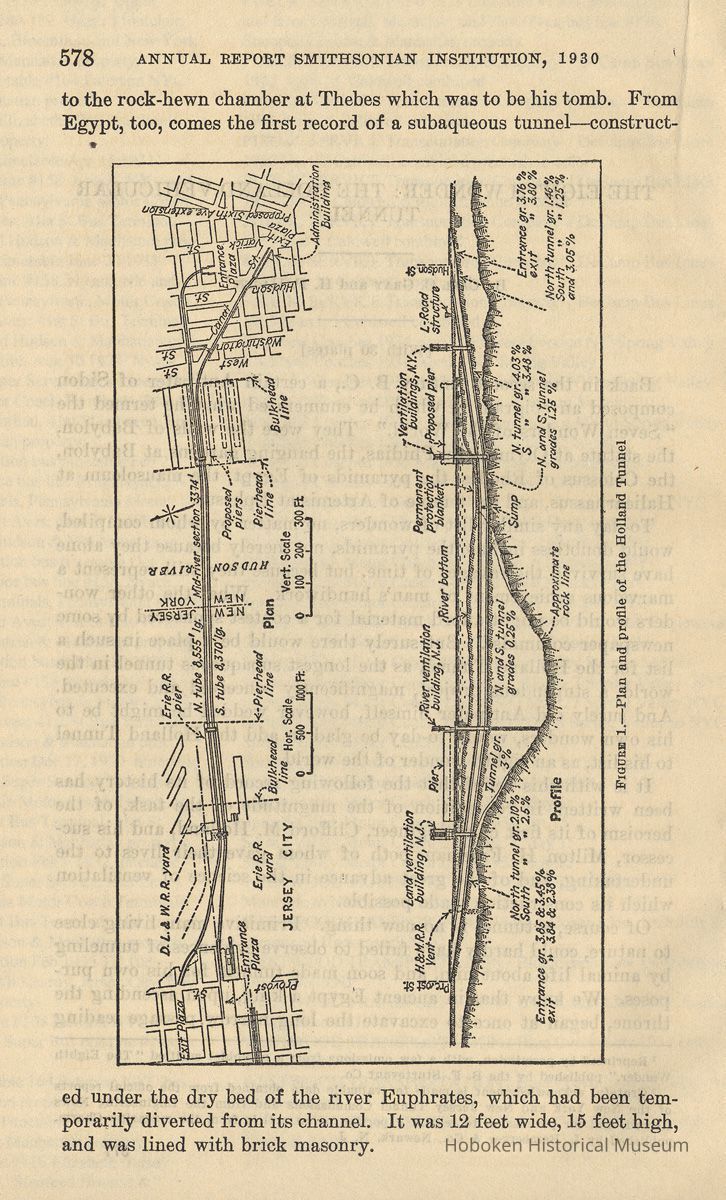
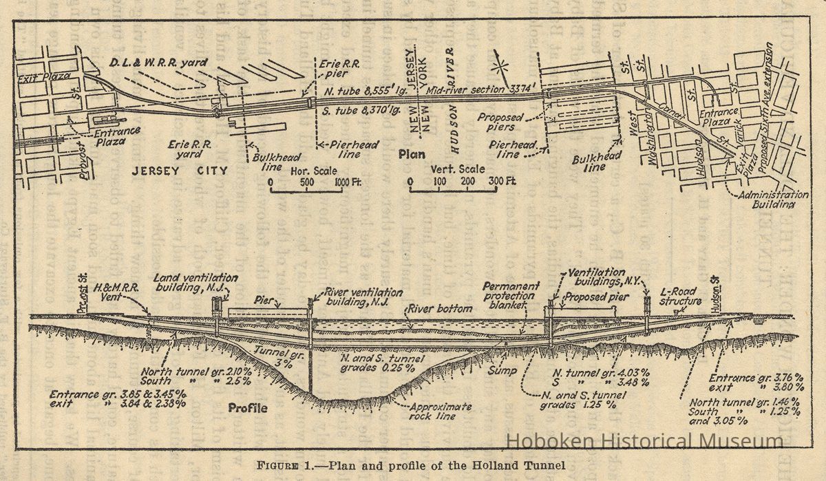
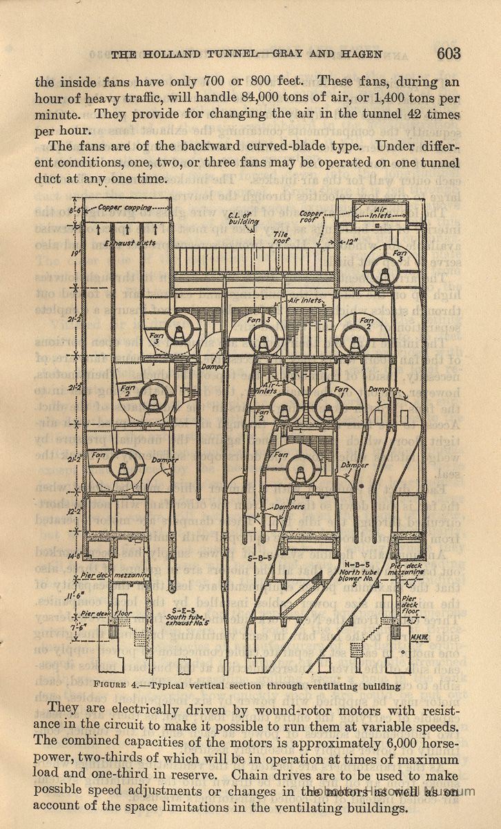
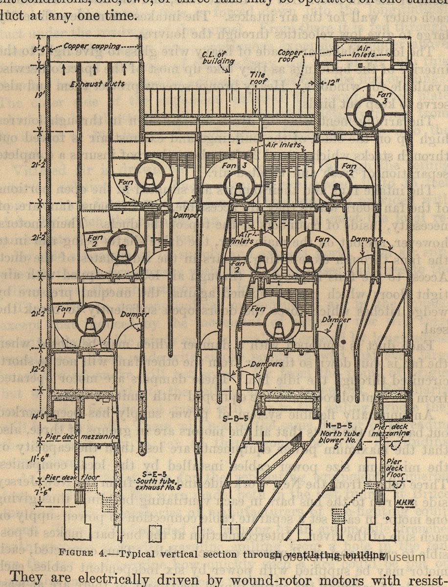
[Illustration] Figure 1. Plan and profile of the Holland Tunnel
under the dry bed of the river Euphrates, which had been tem-
porarily diverted from its channel. It was 12 feet wide, 15 feet high,
and was lined with brick masonry.
THE HOLLAND TUNNEL GRAY AND HAGEN 579
In the time of Caesar Augustus, or perhaps even earlier, the Ro-
mans built a notable tunnel through the Posilipo hills, between
Naples and Pozzuoli, about 3,000 feet long and 25 feet wide. In
order to light this tunnel, its floor and roof were made to converge
gradually from the ends to the middle: at the entrances it was 75
feet high. The Romans were the greatest tunnel builders of an-
tiquity. During the Middle Ages tunnel building was chiefly for
military purposes. Every great castle had its private underground
passage from the central tower or keep to some distant concealed
place, through which to make sorties, receive supplies, or escape in
time of need.
With the advent of gunpowder and of canal construction, a strong
impetus was given to tunnel building in its more modern aspect of
commercial or public utility. Previous to 1800, canal tunnels were all
through rock or hard ground. Then, in 1803, a soft-ground tunnel 24
feet wide was excavated for the Saint Augustine Canal in France.
Timbers were laid to support the roof and walls as fast as the earth
was removed, and the masonry lining built closely following. From
this experience the various systems of soft-ground tunneling since
employed have developed.
The use of shield and metal lining marks the greatest development
in the art of soft-ground submarine tunneling. The shield was in-
vented and first used by Sir Marc Isambard Brunei in excavating the
first tunnel under the river Thames at London, begun in 1825 and
opened in 1843. In 1869 Peter William Barlow used an iron lining
in connection with a shield in driving the second tunnel under the
Thames at London.
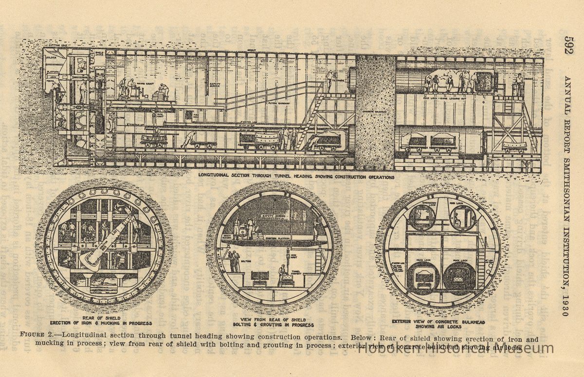
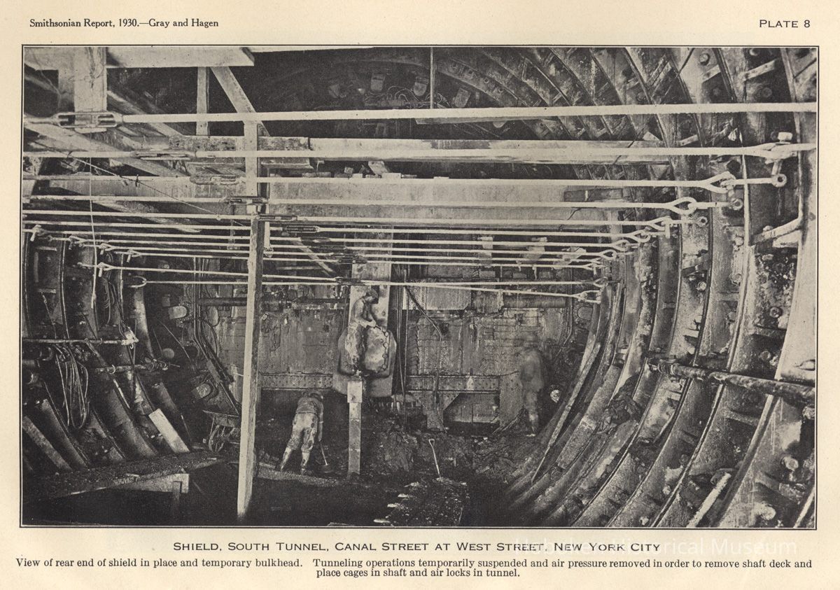
The modern tunnel shield is a steel-plate cylinder whose forward
edge acts as a cutting edge. Its rear end, extending backward, over-
laps the tunnel lining of cast-iron rings. Inside the shield, hydraulic
jacks act against the tunnel lining as a thrust block so as to push the
shield ahead when pressure is applied. A partition prevents earth
from entering the shield except as permitted through suitable open-
ings. As the shield moves forward, the lining is erected under the
protection of its rear. In submarine tunneling compressed air
pumped into the forward end of the tunnel counterbalances the pres-
sure of the water which tries to enter.
In 1906 the Legislatures of the States of New York and New Jersey
created for each State a bridge commission to investigate the feasi-
bility of constructing a bridge over the Hudson River, uniting New
York City with Jersey City. Legislative recognition was thus given
to an increasingly vital problem-some means to supplement the
ferries plying between these two ports.
Further legislation, enacted from time to time, continued the life
of these commissions. In 1913 they were authorized to consider the
possibility of a vehicular tunnel. Finally, on April 10, 1919, author-
580 ANNUAL REPORT SMITHSONIAN INSTITUTION, 1930
ity was granted them to proceed with the construction of a tunnel,
or tunnels, between a point in the vicinity of Canal Street on the
island of Manhattan and a point in Jersey City.
Those who had the project closest at heart felt that the tunnel
would
1. Shorten the time of transit across the Hudson River and afford a con-
tinuous means of communication between New York and New Jersey, unaffected
by climatic or other interference.
2. Relieve traffic congestion, already serious.
3. Accelerate the movement of necessary supplies into the city of New York,
and thereby relieve conditions of distress.
4. Increase the tax value of real property within a considerable radius of
the tunnel terminals.
5. Pay its cost three times over within 20 years.
6. Reduce the high cost of living by reducing the cost of trucking.
7. Increase the facilities for commerce in the port of New York by removing
from the surface of the harbor many lighters and other floating equipment.
8. Furnish means for the uninterrupted movements of troops and supplies
to and from the city of New York in case of need.
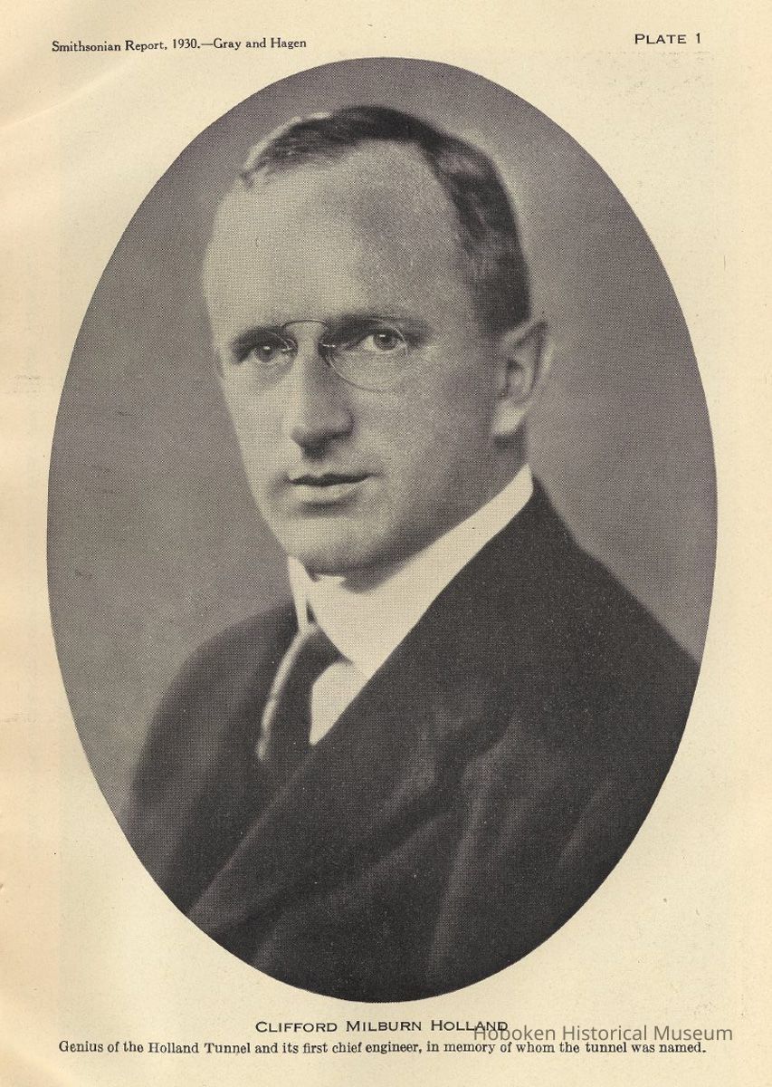
The commission selected as chief engineer, Mr. Clifford M. Holland,
tunnel engineer of the Public Service Commission, First District,
State of New York, in immediate charge of the construction of
all subway tunnels under the East River. He was regarded as
having had a greater and more successful experience in the work of
subaqueous tunnel construction than any other member of his pro-
fession. A board of consulting engineers was appointed, and a
contract or treaty between the two States was drawn up and
approved by the commissions and given the consent of Congress.
Chief Engineer Holland took office on July 1, 1919, and at once
began the organization of an engineering staff. His chief assistants
were selected from those who had been associated with him in the
construction of the East River subway tunnels. Having had not
less than 10 years' experience in subaqueous tunneling, they were
well qualified both by technical training and by practical experience
to meet the requirements of the work. Actual construction began
October 12, 1920.
Upon the death of Mr. Holland on October 27, 1924, at Battle
Creek Sanitarium, where he had gone in search of health after devoting
all his strength and energy to the construction of the tunnel,
the commissions gave it his name. Under his direction all the more
difficult portions had been completed and the remaining details
planned, and on the very day his body was borne to his home there
came a demonstration of his engineering skill and accuracy in the
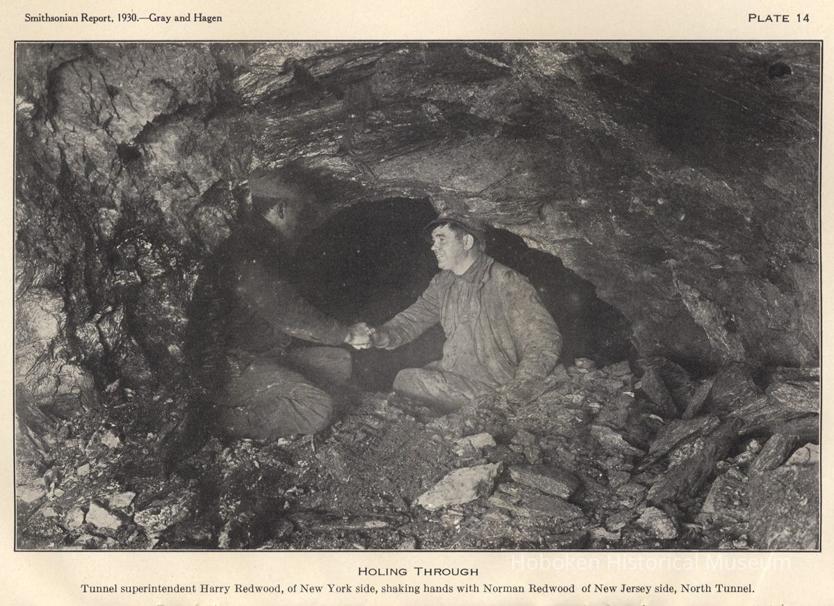
successful junction of the under-river headings of the north tunnel.
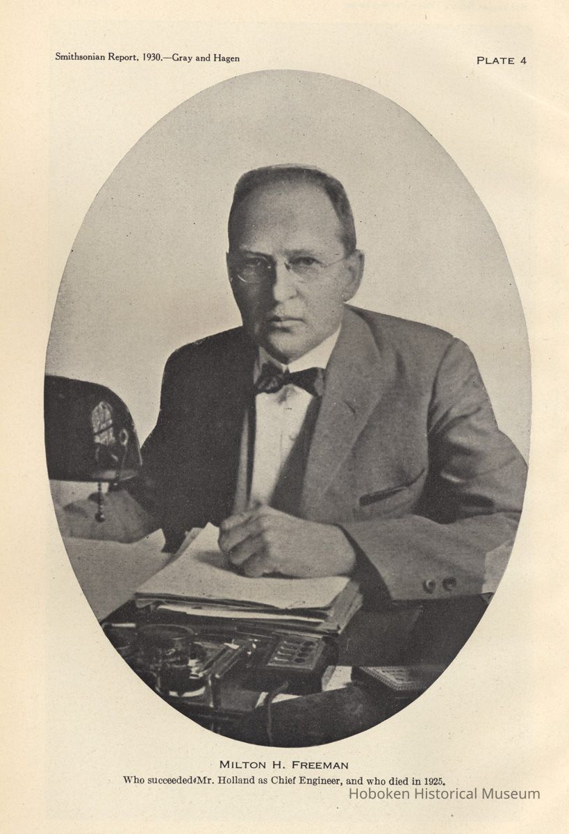
His successor, Mr. Milton H. Freeman, had been his division en-
gineer. He, too, gave himself unsparingly to the work, and died on
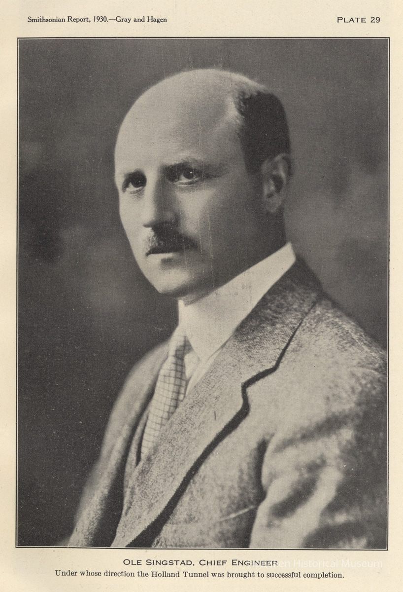
March 24, 1925. He was succeeded by Mr. Ole Singstad, who had
THE HOLLAND TUNNEL GRAY AND HAGEN 581
been engineer of designs under both Mr. Holland and Mr. Freeman.
Under his direction the Holland Tunnel has been completed.
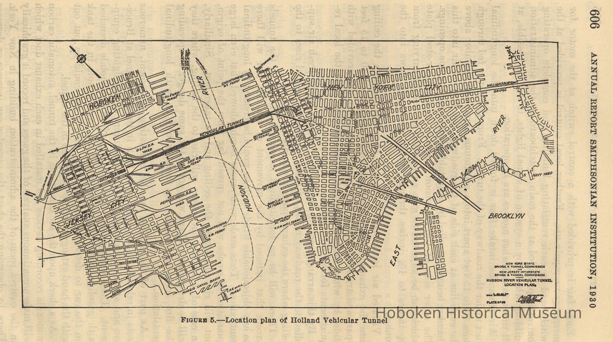
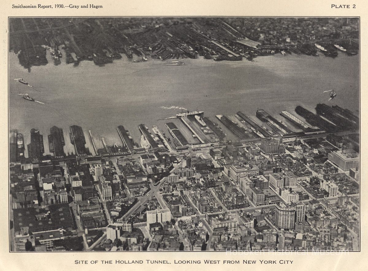
The Holland Tunnel is located in the vicinity of Canal Street,
New York City, because that street is a wide east and west thorough-
fare giving direct communication across the island of Manhattan.
On the east, Canal Street connects with the East River bridges and
Brooklyn; on the west, with the Hudson River water front, at ap-
proximately the center of down-town traffic over the Hudson ferries.
Its location in Jersey City is at the logical point as nearly opposite
Canal Street as is practicable, in order to obtain the shortest tunnel.
This point is very near the center of traffic and is advantageously
located. It gives direct communication to Jersey City Heights and
points beyond by means of the Thirteenth Street viaduct. The water
front, with important railroad yards, is easily accessible and ade-
quate communication is afforded with the low-lying parts of Jersey
City and Hoboken through streets which parallel the river.
The southerly tube for eastbound traffic extends from Provost and
Twelfth Streets, Jersey City, under the Erie Railroad yards, the
Hudson River, and Canal Street to Varick Street, New York City.
The northerly tube for westbound traffic extends from Broome Street
midway between Varick and Hudson Streets in New York City,
curving to the west to Spring and Hudson Streets and under Hud-
son Street and the Hudson River, the Erie, and the Delaware, Lack-
awanna and Western Railroad yards to Fourteenth Street at Prevost
Street, Jersey City.
In planning a public undertaking of the magnitude of the Holland
Tunnel, consideration had to be given to many features besides those
of actual tunneling. The building of the structure itself was a
great engineering problem, but many investigations beyond mere
technical design were required.
To secure the best location and arrangement of tunnel roadways,
a survey of present and future traffic and the influence of the tunnel
on the development of adjacent territory was called for, first of all.
Traffic conditions had to be considered from many angles, such as
capacity, congestion of the tunnel roadway, adequate approaches,
congestion in adjoining streets, width of roadway, and the growth
and development of vehicular traffic.
A preliminary forecast of tunnel traffic, based chiefly on the yearly
increase in traffic over the Hudson ferries, resulted in an estimate of
the number of vehicles that would use the tunnel as follows:
Number
1924 (when tunnel was expected to be opened) 5,610, 000
1935 13, 800,000
1937 15, 700, 000
1943 22,300, 000
28095-31 38
582 ANNUAL REPORT SMITHSONIAN INSTITUTION, 1930
Further estimates indicated that a 1-line tunnel would have a
capacity about equal to the traffic demand at the opening of the
tunnel. A 2-line tunnel would have sufficient capacity to accommo-
date all traffic up to 1937, while a 3-line tunnel would reach its capacity
in 1943.
Obviously it would be unwise to construct a 1-line tunnel whose
capacity would be reached as soon as put in operation. As between
a 2-line and a 3-line tunnel, it was found that the difference in cost,
with interest, would be sufficient to pay for another 2-line tunnel
after the first 2-line tunnel had outgrown its capacity. Of greater
importance was the consideration that no street or section could
accommodate the volume of traffic represented by a 3-line tunnel.
If a 3-line tunnel were built, it could be operated at only 2-line
capacity. This would violate two of the main principles governing
proper tunnel planning-the distribution of traffic so as to avoid
undue congestion, and the investment of capital for construction only
as facilities are needed, without the necessity of providing for the
distant future. These are two of the most important features in
which tunnel construction is held to be superior to bridge construc-
tion in crossing wide, navigable rivers.
The cost of a long-span bridge does not vary directly with the
span but increases about as the square of the span. On such a bridge
no commensurate saving in the cost of construction is obtained by
omitting some of its facilities. The tendency in bridge construction,
therefore, is to provide facilities greatly in excess of immediate
requirements, with a consequent expenditure of capital long before
those facilities are needed. Then when there is sufficient traffic to
utilize the bridge to full capacity, the resulting congestion in the
vicinity of the bridge entrances becomes a serious matter. This is
seen in the case of the East River bridges in New York City to-day.
Tunnel construction, on the other hand, is more flexible than
bridge construction, because the cost is a direct function of its length,
with the volume of excavation increasing as the square of the
diameter. Since the cost of excavation represents a large part of
the total cost of a tunnel, any increase in the width of roadway can
be made only at considerable expense. The proper way to plan a
tunnel is to avoid the disadvantages inherent in bridge construction,
build only for the present and near future, and construct other
tunnels at other locations when the facilities of the first tunnel are
outgrown.
Since a 2-line tunnel would have sufficient capacity to accommo-
date traffic up to 1937, and a 3-line tunnel would create such traffic
congestion in the vicinity of its entrances and exits as to preclude its
use to capacity; also since the difference in cost between a 2-line and
a 3-line tunnel, with interest, would pay for a new 2-line tunnel
THE HOLLAND TUNNEL GRAY AND HAGEN 583
when the first was outgrown, the obvious proceeding was to construct
a 2-line tunnel and when its capacity is reached, to build another
2-line tunnel at some other location as determined by future traffic
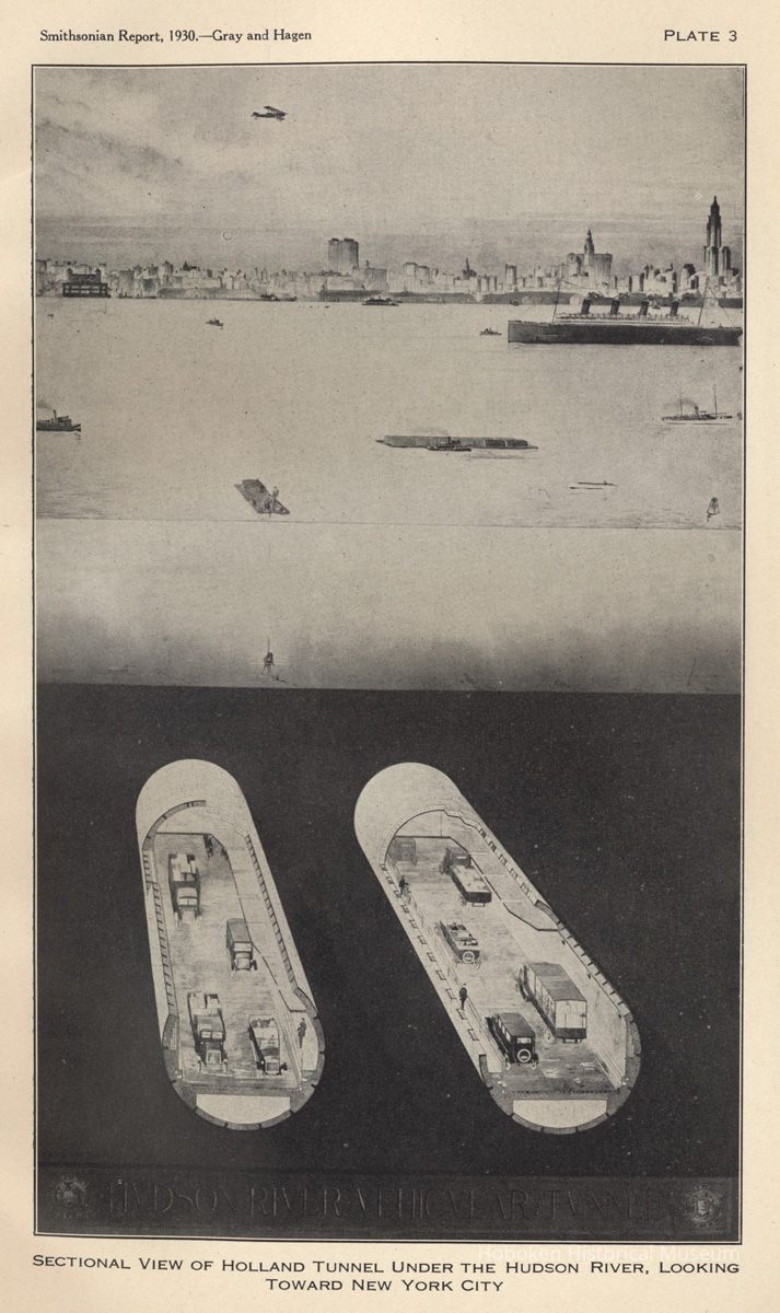
conditions. The Holland Tunnel is, therefore, a twin-tube tunnel,
providing in each tube for two lines of traffic in each direction.
In planning the entrances and exits of the tunnel, a careful study
was made of vehicular traffic, with particular reference to its move-
ment at street intersections and through the tunnel. It was recog-
nized that wherever traffic intersects, its continuity is broken. In-
stead of moving in a steady stream, it breaks into a series of waves
as it is held up and released at intersections. This interruption in
the stream of traffic at street intersections so limits the capacity of a
street that its real capacity as determined by its width is never
reached.
A tunnel differs from a street in that the only interruptions by
cross traffic are at the entrances and exits. Consequently these
points are of vital importance, affecting as they do the ultimate ca-
pacity of the tunnel. Unless the entrances and exits insure con-
tinuity of traffic during the period of maximum demand, the
capacity of the tunnel roadway can never be reached.
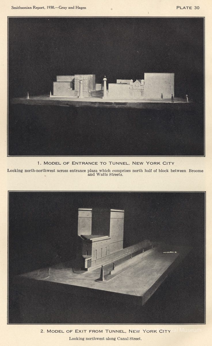
Accordingly, the entrances and exits of the Holland Tunnel are
widely separated. In New York City, one is to the north and the
other to the south of the Canal Street through traffic; in addition
they are located so as to be served by two main north and south
avenues. Tunnel traffic is thus given the best possible facility for
free movement while at the same time the greatest separation is se-
cured at a reasonable cost. In accord with this same principle the
entrance and exit at the Jersey City end are located in separate
streets adjacent to the railroad yards east of the north and south
traffic streets connecting Jersey City with Hoboken.
This separation of the tunnel entrance and exit traffic is consid-
ered to be a factor of the greatest importance in relieving congestion
in the vicinity of the tunnel. This was particularly necessary in
New York City, with its large and rapidly increasing volume of
traffic. It was also called for in Jersey City, where there were no
wide thoroughfares in the vicinity of the tunnel.
In addition, property was taken to provide broad plazas at en-
trances and exits. The entrance plazas serve to accommodate the
waves of traffic as they approach the tunnel and converge in the
portal roadway into continuous lines of vehicles through the tunnel.
Similarly wide exit plazas insure the free and uninterrupted move-
ment of traffic away from the tunnel. Through the separation of
entrance from exit, and the use of adequate plazas, the tunnel traffic
can be distributed over a large number of streets.
584 ANNUAL REPORT SMITHSONIAN INSTITUTION, 1930
In considering the requirements for the width of the roadways
and the clear headroom needed, measurements were taken of vehicles
crossing the Hudson on the ferries between New York and New
Jersey. It was found that their height varied from 6 feet 6 inches
for passenger cars to a maximum of 13 feet for large loaded trucks,
but that the number exceeding 12 feet in height was only 1 per cent.
The width of motor vehicles varied from 6 feet for passenger cars
and light trucks to a maximum of 10 feet 6 inches for army transport
trucks. In the case of 3-horse teams, the outside dimension of the
three horses abreast was 9 feet, but the number of vehicles exceeding
8 feet in width was only 3% per cent.
In determining the amount of clear headroom required, it was
necessary to consider the matter of providing sufficient area in the
tunnel roadway. Any increase in clear headroom, without increas-
ing the size of the tunnel, could be made only at the expense of the
available ventilating duct area. Any reduction in this area would
increase the power required for ventilation and add to the cost of
operating the tunnel.
Given a maximum height of 12 feet 2 inches and a maximum width
of 8 feet, a clear headroom of 13 feet 6 inches seemed adequate to
allow even for jacking up vehicles in case of breakdown, and this
was decided upon.
Normal operating conditions in a tunnel accommodating two
lines of vehicles in the same direction on one roadway obtain when
there is a slow line of heavy trucks 8 feet wide abreast of a fast line
of light trucks and passenger cars 6 feet wide. It is, however,
necessary to provide for such a contingency as when a vehicle of
maximum width has to pass another of the same width that has
stalled. The roadway has to be sufficiently wide to permit the pas-
sage abreast of two vehicles of maximum width.
It was believed that in the slow line, operating at a speed varying
from 3 to 6 miles per hour, a clearance of not less than 6 inches
between the outside of the tire and the curb should be provided. In
the fast line, due to the greater speed, this clearance should not be
less than 1 foot. It was also considered that for safe and convenient
operation a clearance between moving vehicles of 2 feet 9 inches
should be allowed. These considerations led to the adoption of a
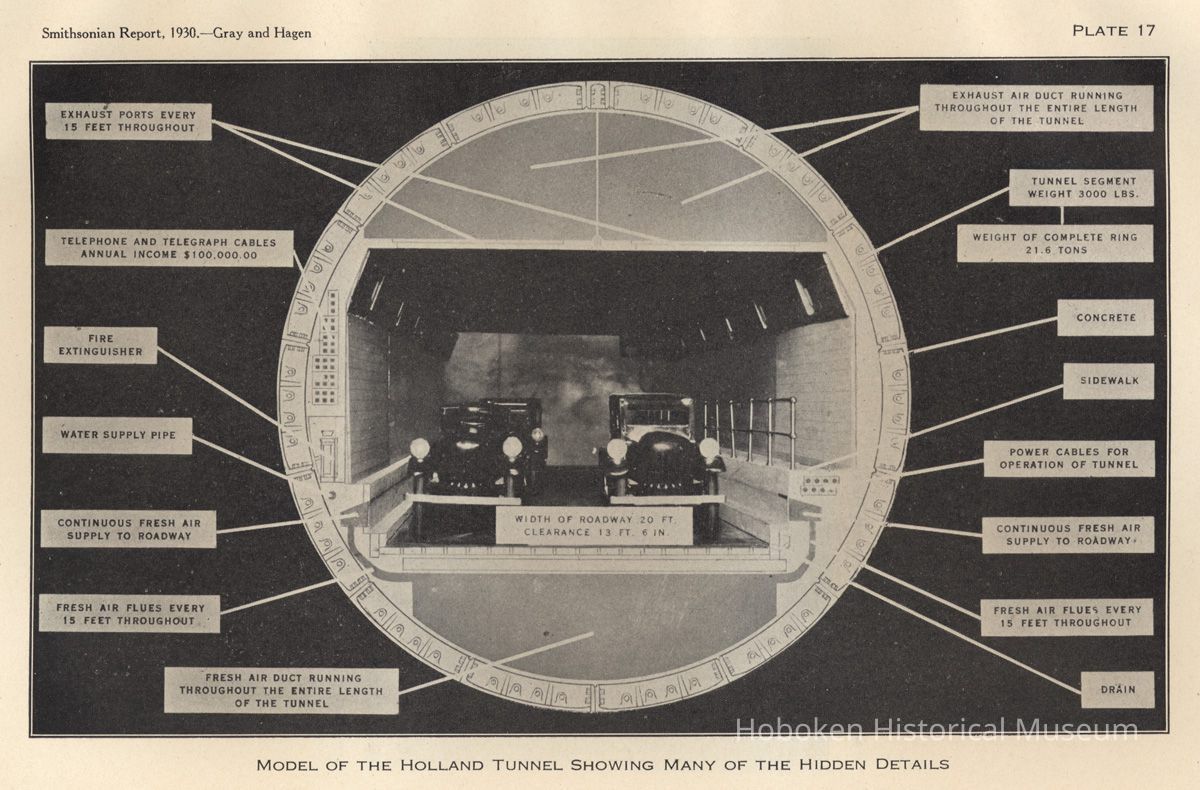
width of roadway of 20 feet, with, in addition, a sidewalk 2 feet
wide in each tunnel. This sidewalk is set back from the curb line
a distance of 6 inches and is located at an elevation of 26 inches
above the roadway.
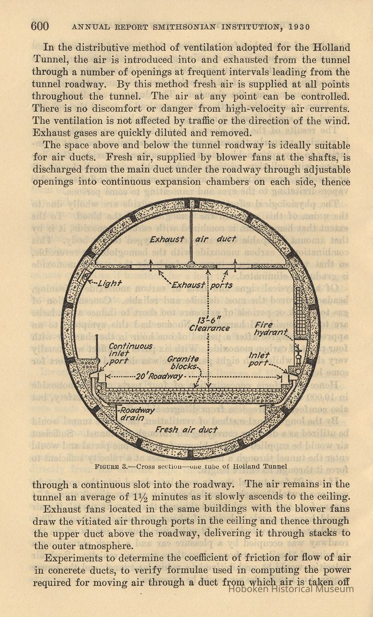
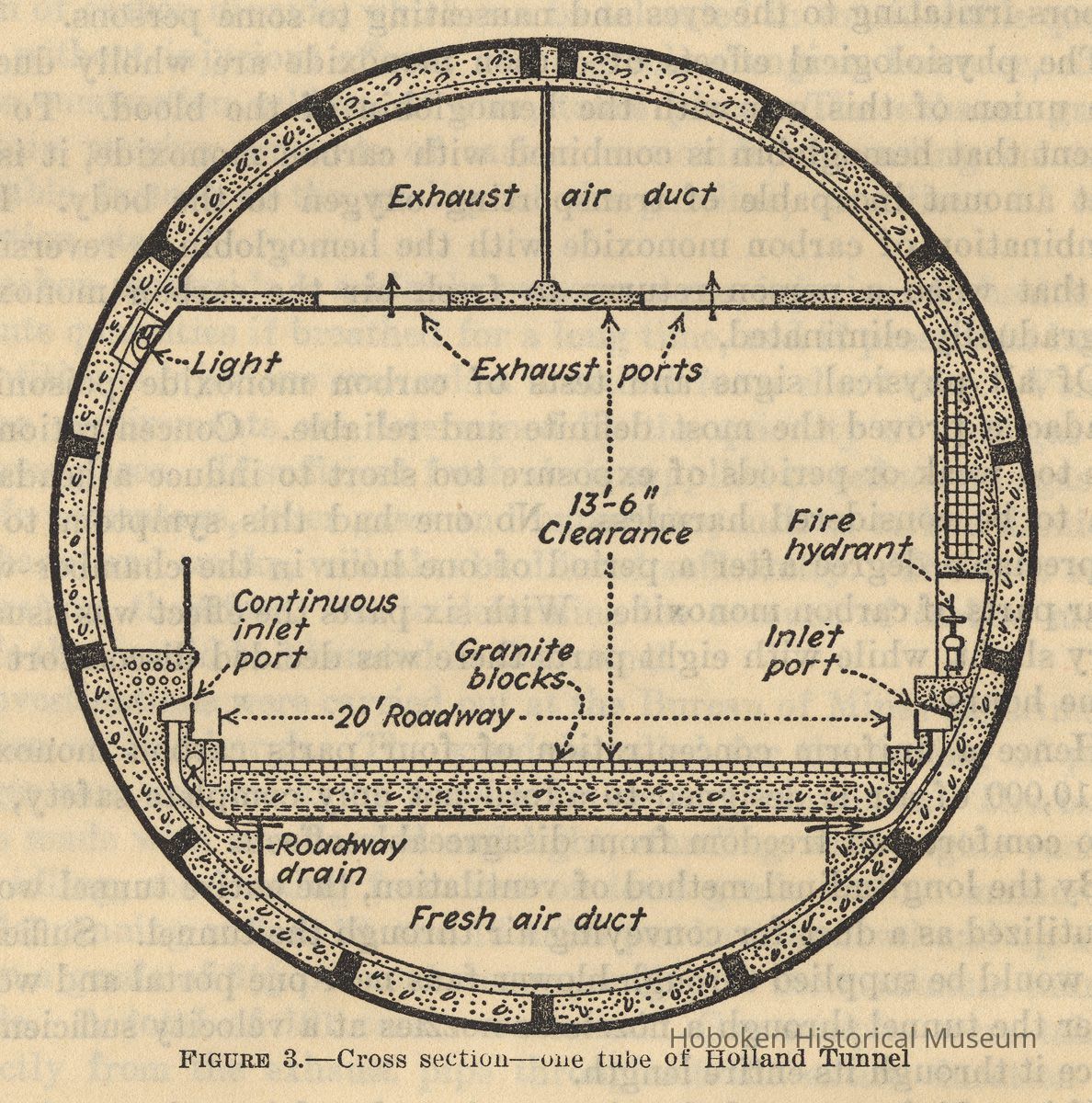
This roadway is paved with granite blocks laid in the usual sand
cement cushion layer, about 1 inch thick, with the joints filled with
hot asphalt mixed with heated sand. By means of squeegees, a thin
coating, sprinkled with sand, is left upon the surface, resulting in a
THE HOLLAND TUNNEL GRAY AND HAGEN 585
smooth, resilient, and long-wearing surface that will help to deaden
the sounds due to traffic, and be more quickly repaired than concrete.
Each side of the roadway is lined with a granite curb, the roadway
having a transverse slope from one side to the other, with a de-
pressed concrete gutter behind the curbstone on the low side with
side inlet openings at frequent intervals. The drain connects with
a sump at the low point of the tunnel, from which a discharge pipe
is carried under the roadway of each tunnel to the New York River
shaft. Intercepting sumps with pumping equipment are provided
in all the river and land shafts.
The tunnel is lighted by electric lamps located in the side walls of
the tunnel immediately below the ceiling slabs. A continuous water
main is provided throughout the entire length of each tube, with hose
connections for fire protection and flushing at frequent intervals.
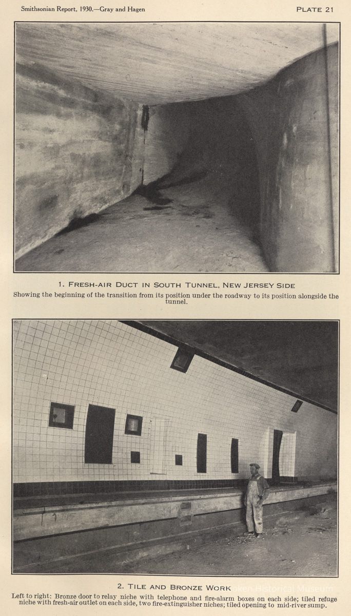
The walls are lined with white tile, care being taken to eliminate
all tile containing blue, green, or red tints, upon advice of a " color
psychologist," on account of its " depressing effects." The color of
the borders is a light orange. The ceiling is painted white.
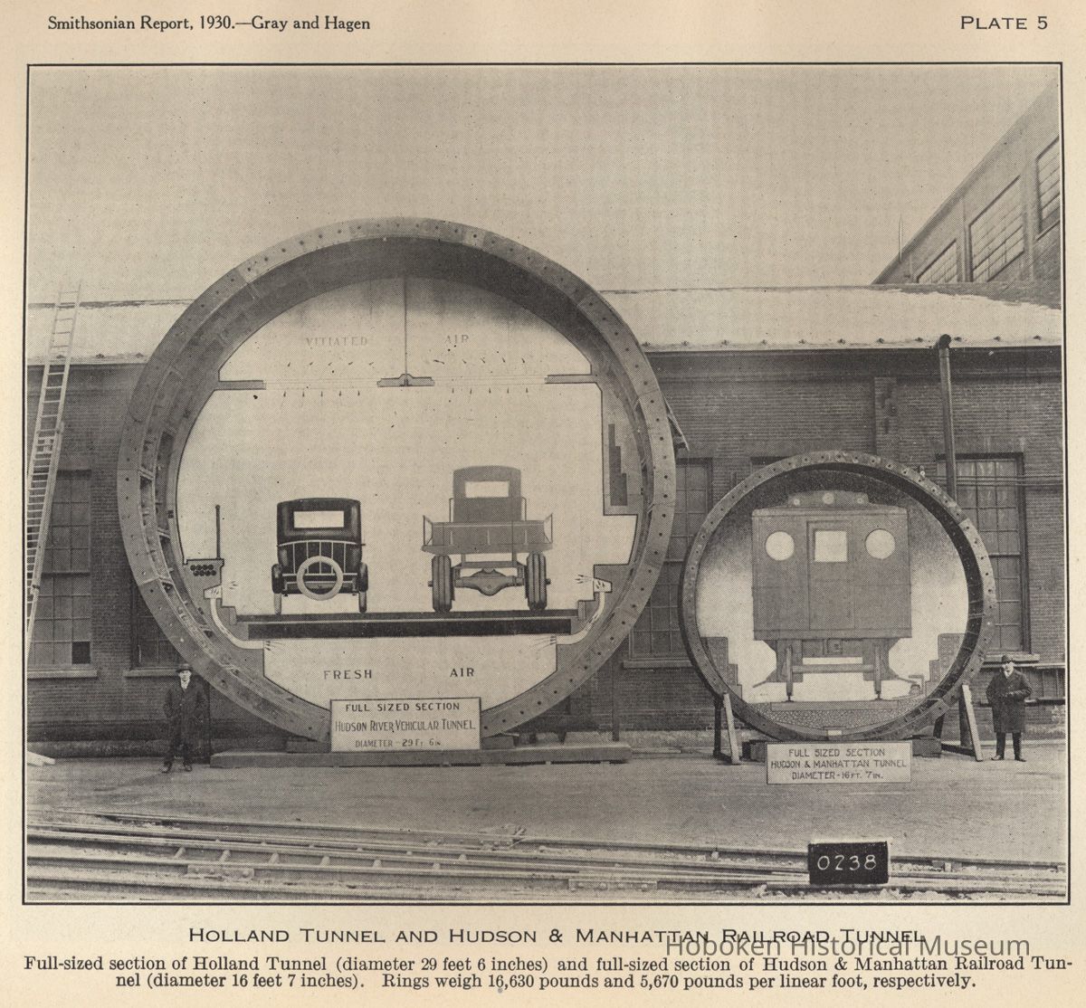
The tunnel, with its twin tubes, 29 feet 6 inches in diameter, is the
largest subaqueous tunnel in America, exceeding by 6 feet 6 inches the
Pennsylvania Railroad tubes. On the New Jersey side, the diameter
of one of the tubes is increased to 30 feet 4 inches to meet ventilation
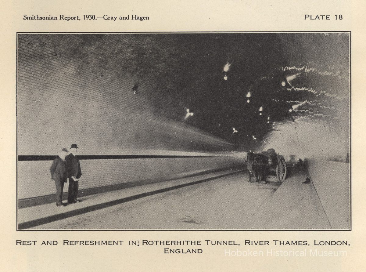
requirements. This exceeds by 4 inches the diameter of the Rother-
hithe Tunnel under the river Thames, London, England, which has
been the largest subaqueous tunnel in the world.
The shield method of construction was adopted for the Holland
Tunnel after careful consideration of other schemes, notably the
trench method. By the trench method, the work is conducted from
a plant floating in the river, and the tunnel is constructed either
under a protecting roof or floated into position and sunk in sections
in a dredged trench. The longest subaqueous tunnel built by this
method is the Detroit River tunnel of the Michigan Central Railroad.
It was recognized that in the excavation of a trench under the
Hudson River, there would be an unavoidable interference with a
great volume of river traffic. Fifteen hundred boats cross the line of
the tunnel daily. Such congested river conditions would make every
dredge or other machine working in the tunnel an obstruction to
traffic. Collisions would be frequent, increasing the time and cost of
the work, with danger both to shipping and to the equipment of con-
struction. Storms, fog, and ice would cause a discontinuance of sur-
face work for at least two months of each year. At the New York
end, a large mass of ledge rock, involving blasting and removal at
great depth, would be a serious obstacle to open-trench excavation
under water.
586 ANNUAL, REPORT SMITHSONIAN INSTITUTION, 1930
Since there was a real hazard involved in carrying on operations
from a plant anchored in midstream, the shield method was clearly-
called for. In addition, silt conditions in the Hudson River were
regarded as extremely favorable to this method. In a trench tunnel,
soft material greatly increases the volume of excavation, while in the
case of a shield tunnel this material is most easily excavated. If the
silt is not shoved aside by the shields, it is easily disposed of through
the tunnel. The shield may be closed with the exception of certain
openings through which the material is squeezed into the tunnel as
the shield advances.
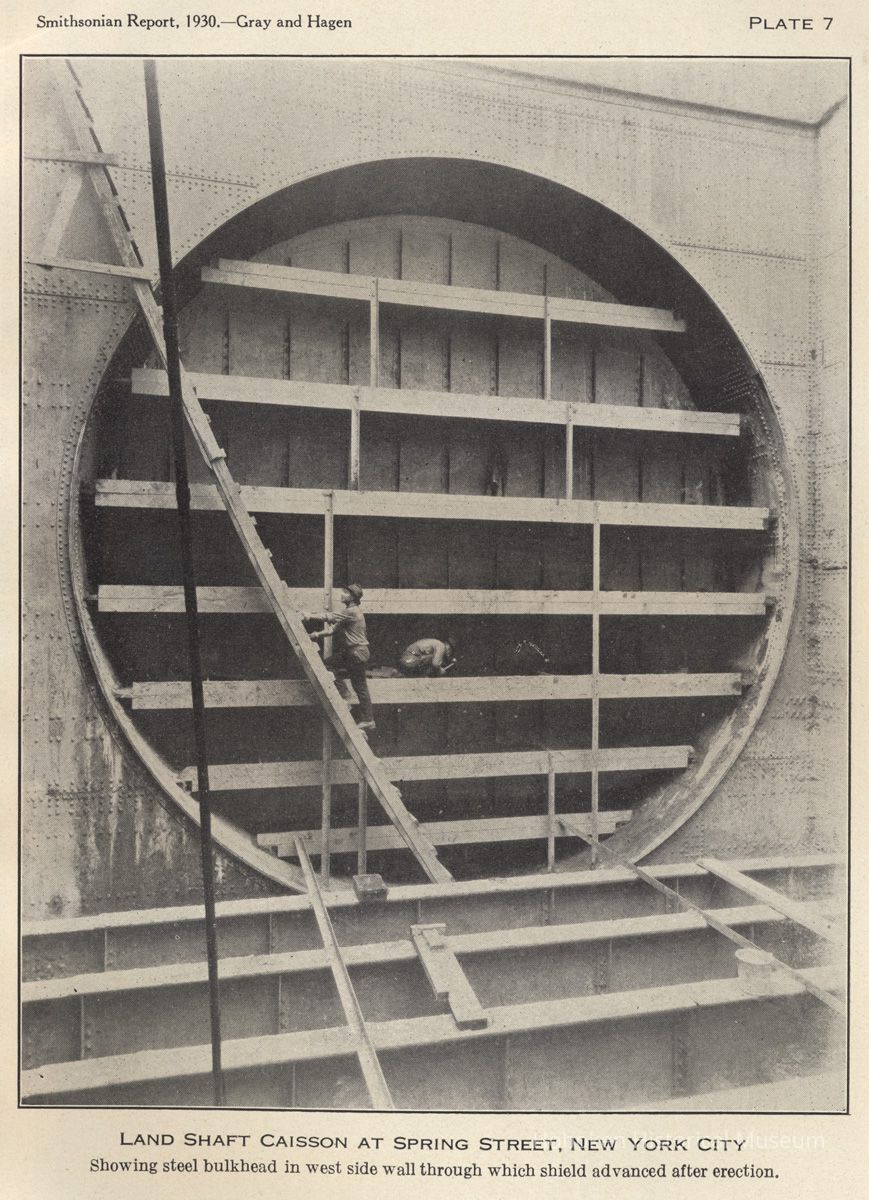
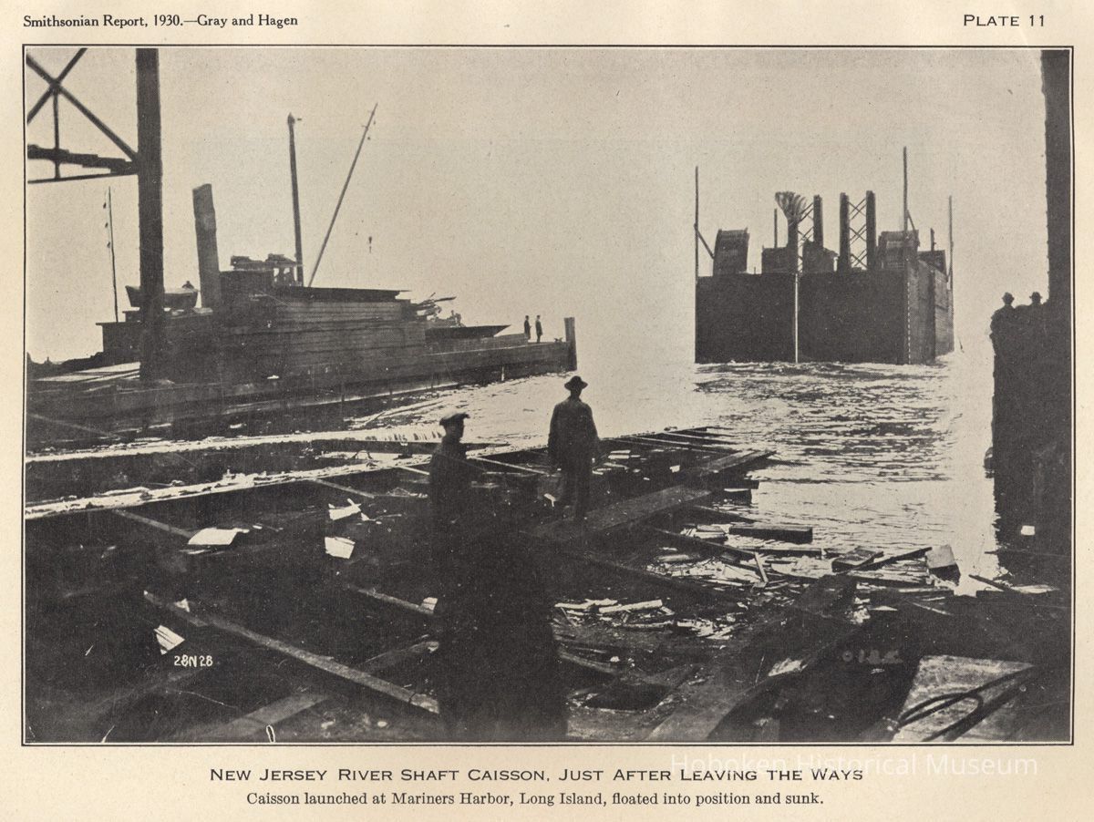
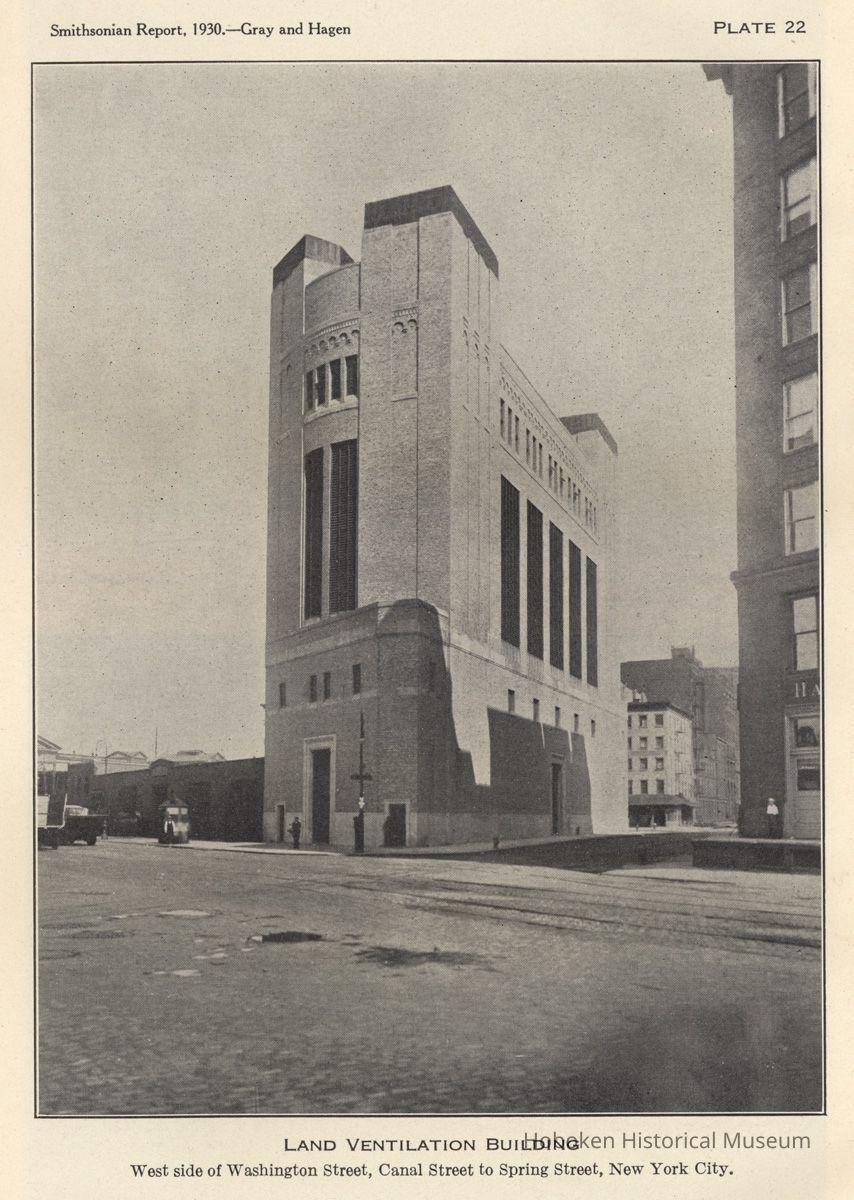
The first contract provided for the sinking of two land shafts,
one at Washington and Canal Streets and the other at Washing-
ton and Spring Streets, New York City. They were sunk by the
compressed-air method.
The double steel walls of the caissons were filled with concrete as
the caissons were sunk. This added to their weight when sinking
weight was needed, and at the same time completed the structure of
the walls. In addition to this concrete, weight for sinking was ob-
tained by storing the excavated material from the working chamber
on the roof of the chamber as the caisson went down. This necessi-
tated handling the material a second time, but gave the desired
weight and permitted the lowering of the caisson without greatly
reducing the air pressure in the working chamber, thereby prevent-
ing loss of ground.
Upon the removal of the compressed air, the bottom seals of the
caissons proved to be water-tight. The shafts were now ready for
the building of the shields preparatory to the beginning of shield
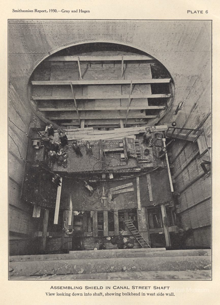
tunneling. Temporary bulkheads were provided in the west side
walls to permit the passage of the shields, and in the east side walls
to connect with the approach section which was to be constructed
by excavation from the surface.
This work was followed by placing under contract the entire un-
der-riv'er portion of the tunnel. Power plants had to be constructed
to produce low-pressure air for caissons and tunnel, high-pressure
air for the operation of grouting machines, air drills, and hoisting
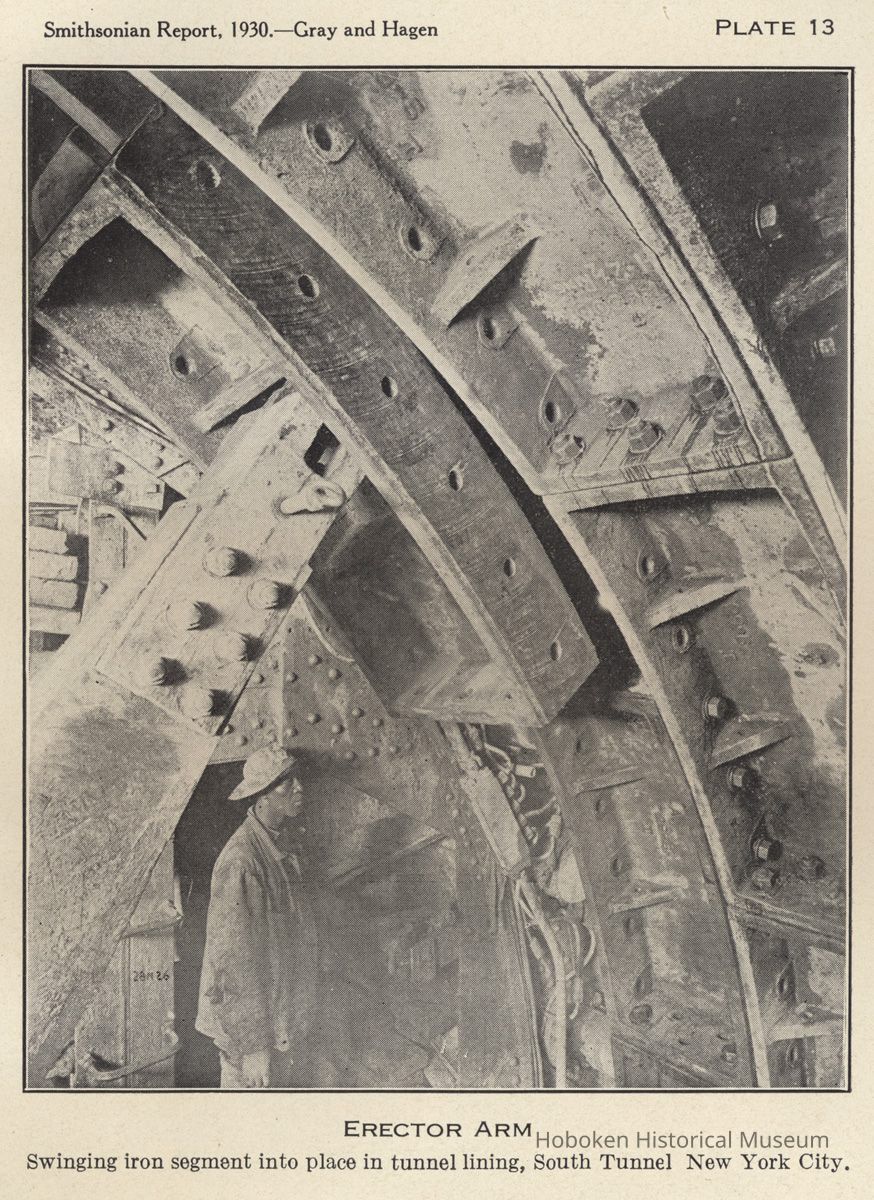
engines used below the surface, and hydraulic pressure for operat-
ing the jacks used in driving the shield and for operating the erector
arm for building the tunnel lining.
Overhead gantries and dumping platforms for the receipt and
disposal of materials and buildings for housing the workmen had
to be provided. Pipes, through which compressed air would be
supplied to the tunnel headings, had to be laid to the shafts. On
the New Jersey side this involved laying low-pressure lines as large
as 16 inches in diameter, high-pressure lines, hydraulic lines, water
THE HOLLAND TUNNEL - GRAY AND HAGEN 587
lines, electric cables, and telephone cables. Every facility had to
be provided, even an independent telephone system connecting all
parts of the work with the public telephone system.
Canal Street Park was made available as a site for the air-com-
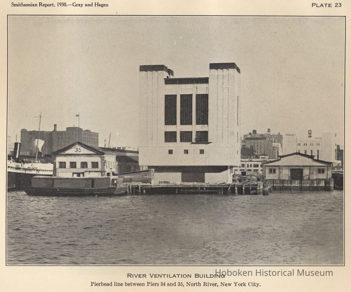
pressing plant and engineer's field office. Pier 35 and adjacent slips
were used for the storage of materials and for the disposal of ex-
cavated matter from the tunnel heading. Overhead gantries con-
necting the shafts with the pier permitted traffic to the water front
in connection with the tunnel to pass above the city streets.
The first shield was erected in the Canal Street shaft. On Oc-
tober 26, 1922, compressed air was introduced into the shield cham-
ber, and tunneling was begun. Each shield was 30 feet 2 inches
in outside diameter, 16 feet 4 inches long, and the upper half was
equipped with a hood projecting 2 feet 6 inches ahead of the shield
proper. Five vertical and three horizontal walls divided the shield
into 13 compartments, through which the ground in front was ex-
cavated. It was equipped with thirty 10-inch jacks, having a
combined thrust of 6,000 tons. A hydraulic erector was used
to build the tunnel segments into a complete ring. The weight
of the shield, with all equipment, was about 400 tons.
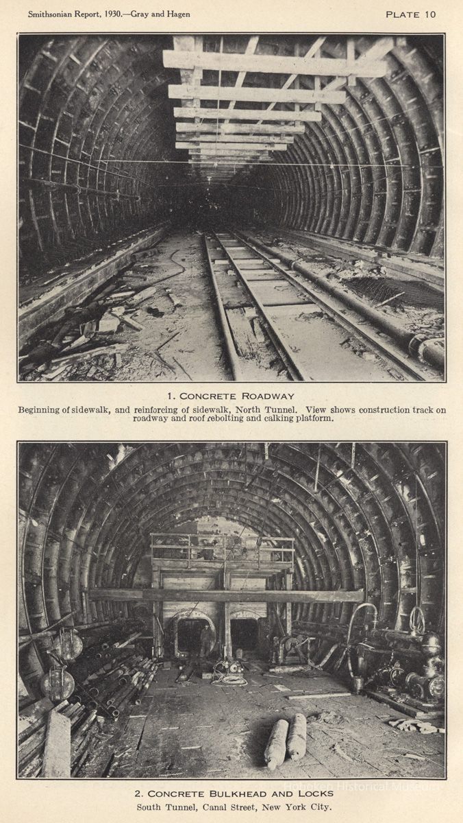
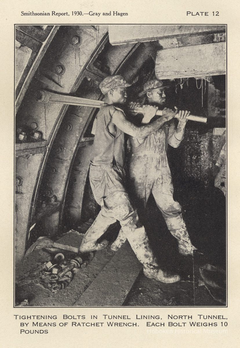
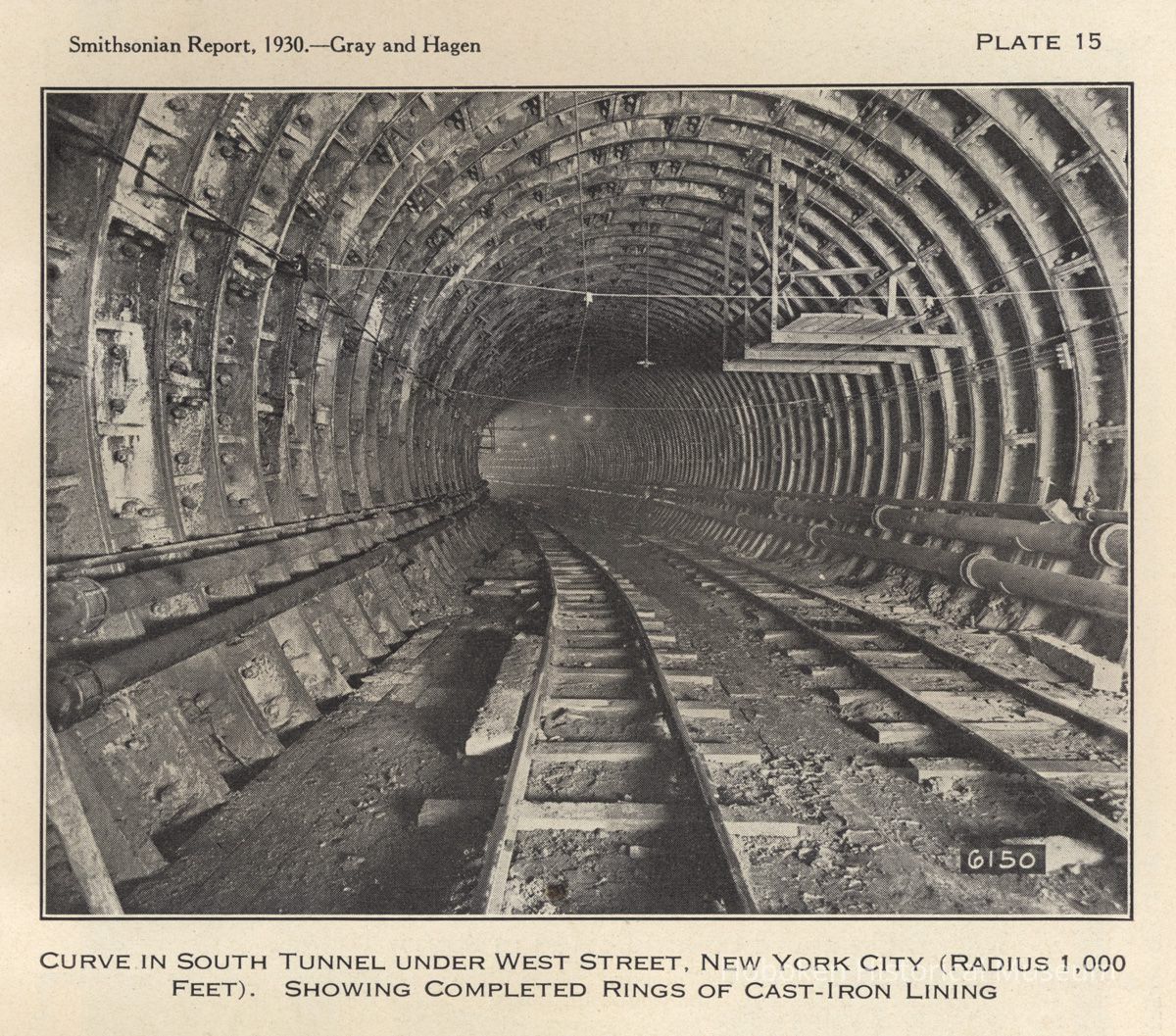
The tunnel lining is composed of rings 2 feet 6 inches wide,
consisting of 14 segments, each approximately 6 feet long, with
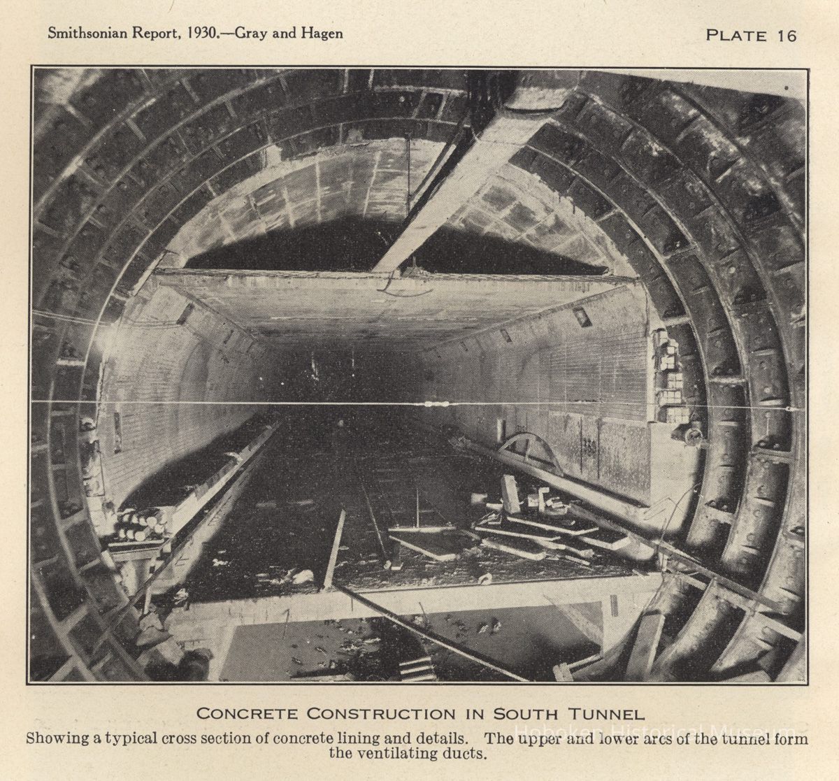
a key 1 foot long, bolted together. Inside the lining is an inner
lining of concrete 19 inches thick. As the shield advanced and
the lining was erected behind it, the space due to the difference in
the diameter of the shield and the rings forming the lining was
filled by forcing a grout of cement and sand in equal parts into the
void under high air pressure. For this purpose each segment
was provided with a grout hole fitted with a screw plug. The lining
was made water-tight by placing hemp grommets soaked in red
lead around the bolts, and by caulking lead wire into grooves be-
tween the segments.
Shield driving requires extreme care and exactitude to keep to
line and grade. The position of the shield fixes the location of the
tunnel, and no correction can be made afterward. It is absolutely
essential that the slightest deviation of the shield from its theoreti-
cally correct position be known at once, so that measures may be
taken to remedy the error during the next shove. The shield is
guided by the operation of the jacks distributed around its cir-
cumference, omitting the use of those jacks in the direction toward
which the shield is to move.
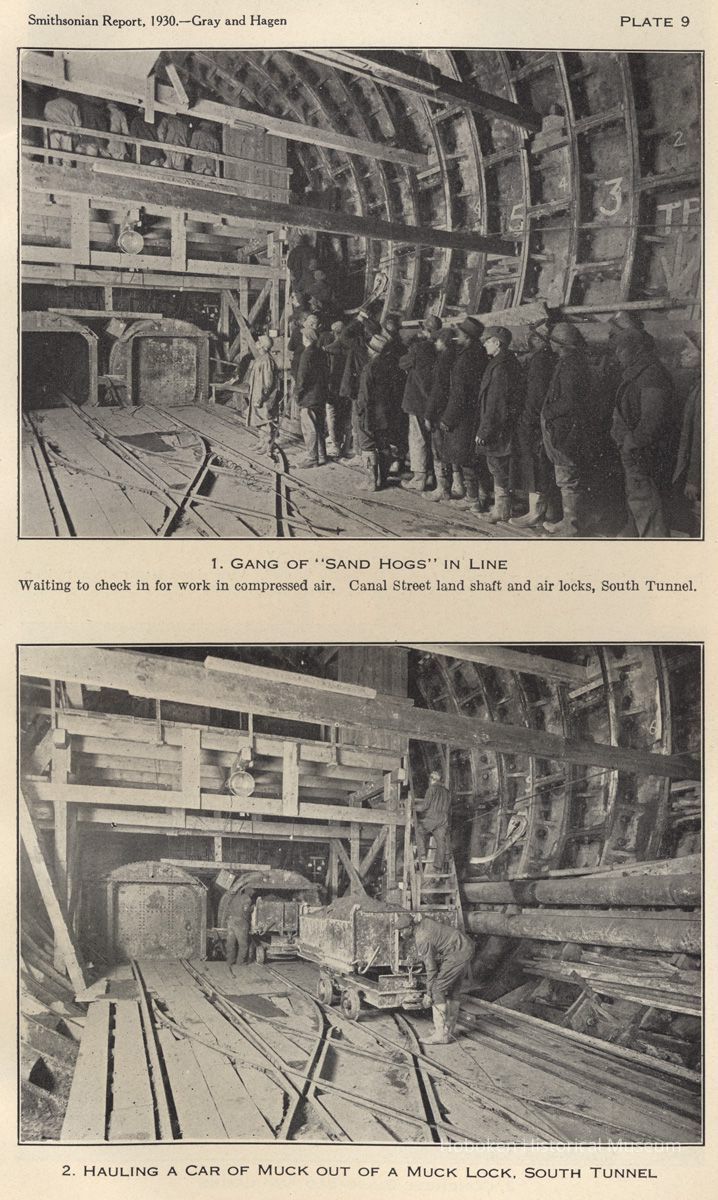
Every precaution was taken to provide for the safety of the work-
men in the compressed-air chambers. A high emergency gangway in
the upper part of the tunnel led from the shield to the locks, for
escape In case of a blowout. Safety screens were installed to trap the
588 ANNUAL REPORT SMITHSONIAN INSTITUTION, 1930
inrushing water. Fire lines were installed in the compressed-air
chambers. Fire is a real danger in compressed-air work on account
of the increased amount of oxygen present. As an indication of the
fire hazard, a candle, if still glowing when extinguished, will again
burst into flame.
The starting of the shields out of the caissons at the New York
land shafts was difficult because of the large diameter of the shields
and the shallow cover overhead. The material at this point was
granular, consisting largely of fine sand, which if undisturb... [truncated due to length]