Name/Title
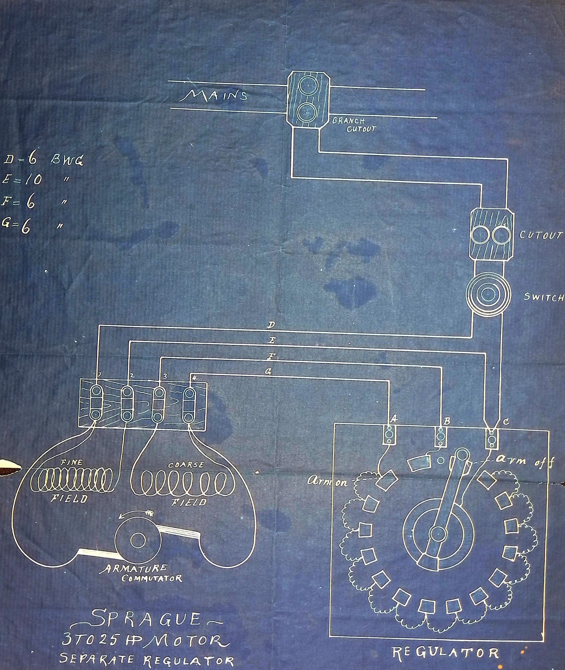
3-25 H.P. Motor Separate Regulator, (1 folder, ca. 1890)Scope and Content
The "Mains" section at the top shows the power source, which connects through a branch cutout and a switch/cutout mechanism for safety.
The motor section features labeled fine and coarse field windings surrounding an armature commutator, which helps regulate electrical flow.
The regulator, depicted on the right, is an essential component for controlling motor speed and efficiency. It features multiple contact points (A, B, C) and an arm adjustment mechanism, likely allowing step-by-step voltage control.
Various wire gauges (D, E, F, G) are specified, indicating the type of wiring required for different connections.Context
This blueprint is an electrical schematic diagram for a Sprague electric motor system, used between 3 to 25 horsepower (HP), with a separate regulator. The Sprague Electric Motor was a significant innovation in electric railways, elevators, and industrial applications in the late 19th and early 20th centuries. Frank J. Sprague, a former employee of Thomas Edison, pioneered the use of electricity for moving streetcars and elevators during the 1880s and 1890s. Latimer probably had this blueprint because Edison’s businesses continued to do work with the Sprague Electric Railway & Motor Company.Collection
Latimer Family Papers (1870-1996 ) [QPL Full Collection]Location
Folder
410os/4Box
410Archival Collection
Latimer Family Papers (1870-1996 ) QPL CollectionLibrary
Queens Borough Public LibraryCity
Jamaica, QueensState
New York, USAContinent
North AmericaCountry
United States