Note
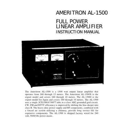
The Ameritron AL-1500 is a 1500 watt output linear amplifier that operates from 160 through 15 meters. The Ameritron AL-1500X is the export model and covers 160 through 10 meters. The AL-1500J is the export model for Japan and covers 160 through 10 meters. The amplifier uses a single 3CX1500A7/8877 tube in a class AB2 grounded grid circuit. CW, FM and RTTY efficiency is improved by shifting the bias deeper into class B. The heavy duty power supply and RF components, combined with a forced air system utilizing a chimney, provide long service life for expensive components. The AL-1500 is shipped factory wired for 240 volt, 50/60 Hz power mains.
Features
– High power gain: the 3CX1500A7/8877 features high power gain. As little as 65 watts of drive power will pr vide 1500 watts of output power.
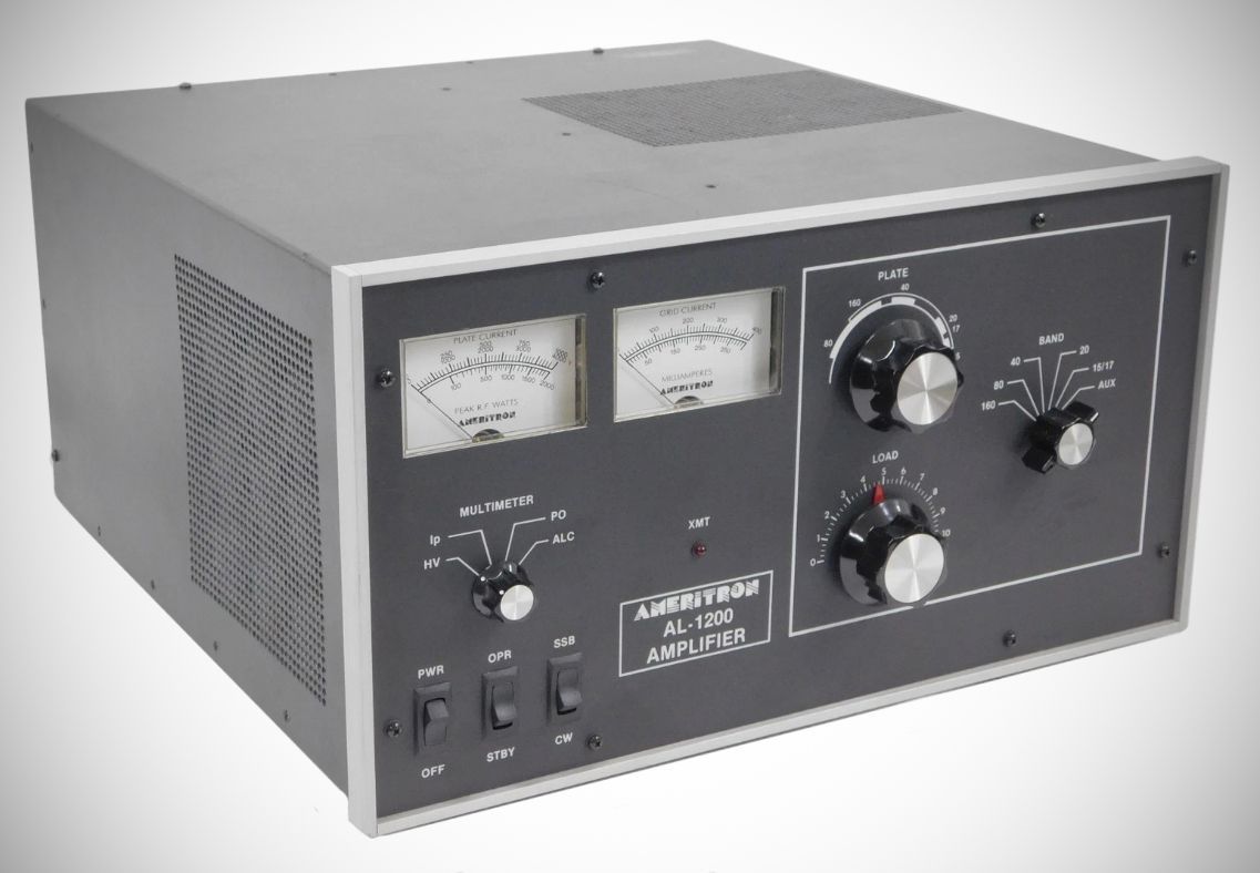
– SSB/CW switch: the bias voltage is switched to provide the best linearity on SSB or the lowest dissipation on CW operation. proper operation of the amplifier. The other meter reads Plate Voltage (HV), Plate Current (IP), Peak RF Watts (PO) and ALC.
– Operate/Standby Switch: filament and plate voltages are maintained while allowing the amplifier to be bypassed for "barefoot" operation.
– 12 Volt Auxiliary Jack: 12 volts at 100 mA is provided for accessories such as the ATR-15 Antenna tuner.
– ALC Indicator: the drive level is detected to provide a control voltage for the exciter. ALC prevents overdriving of the linear and reduces distortion from excessive drive power.
– Vernier Plate and Load Adjustments: both tuning controls have vernier 6:1 reduction drives for smooth tuning.
– Two Illuminated Panel Meters: the AL-1500 has two illuminated panel meters. The Grid Current meter provides a continuous reading of grid current and indicates
– XMT Indicator LED: provides a front panel indication of proper amplifier keying by the exciter during operation.
– Grid Overload Circuit: this amplifier has a circuit that protects the tube from excessive grid current. If 175 mA of peak grid current is reached the "OPR" LED will no longer light and the amplifier will go into a bypass condition. This overload condition can be reset by momentarily putting the STBY/OPR switch in the STBY position.
Specifications
Input
Circuit type: Pi-network, slug tuned coils.
Maximum VSWR at resonance: 1.3:1.
Minimum 2:1 VSWR bandwidth: 20% of center frequency.
Maximum drive power permissible: 100 watts.
Typical drive for full power output: 65 watts.
Output
Circuit type: Pi-L, Pi.
12 hour continuous carrier: 1500 watts.
30 second continuous carrier: 2500 watts.
1/2 hour PEP two-tone test: 2500 watts plus.
30 second PEP two-tone test: 2500 watts plus.
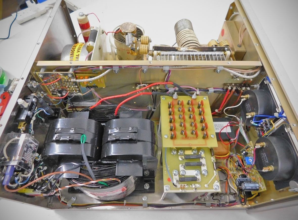
Power Supply
Circuit type: Full wave bridge, capacitor input.
No load voltage: 3600 V.
Full load voltage: 3300 V.
Full load current: 1 amp.
Regulation: 10% typical.
Transformer: 34 lbs., hypersil.
Capacitors: 26 mfd total, computer grade.
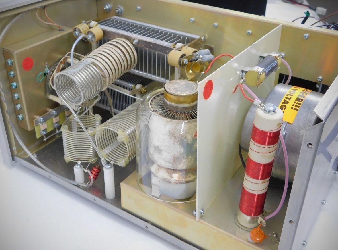
Tube
Type: (1) 3CX1500A7/8877.
Continuous dissipation: 1500 Watts.
Warm-up time: 180 seconds.
Operating Specifications
Efficiency (CW): 65% typical.
Efficiency (SSB at envelope crest): 62%.
Frequency Coverage (Standard AL-1500): 1.8, 3.5, 7, 14, 18, and 21 MHz (user modified models cover 24 and 28 MHz).
Third Order IMD at Rated Output: –36 dB.
MARS/WARC: Yes, set to nearest highest amateur band.
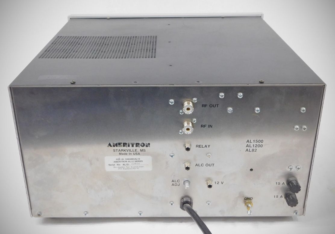
Physical and Connectivity
RF Connectors: SO-239.
Line Connector: NEMA 6-15P, 240V style.
Maximum draw at rated output: 15 amps at 240V AC 50/60 Hz.
Keying: Requires relay closure or sinking to ground of +12V DC at 100 mA, phono jack.
ALC: Negative going, 0-20V, adjustable, phono jack.