Note
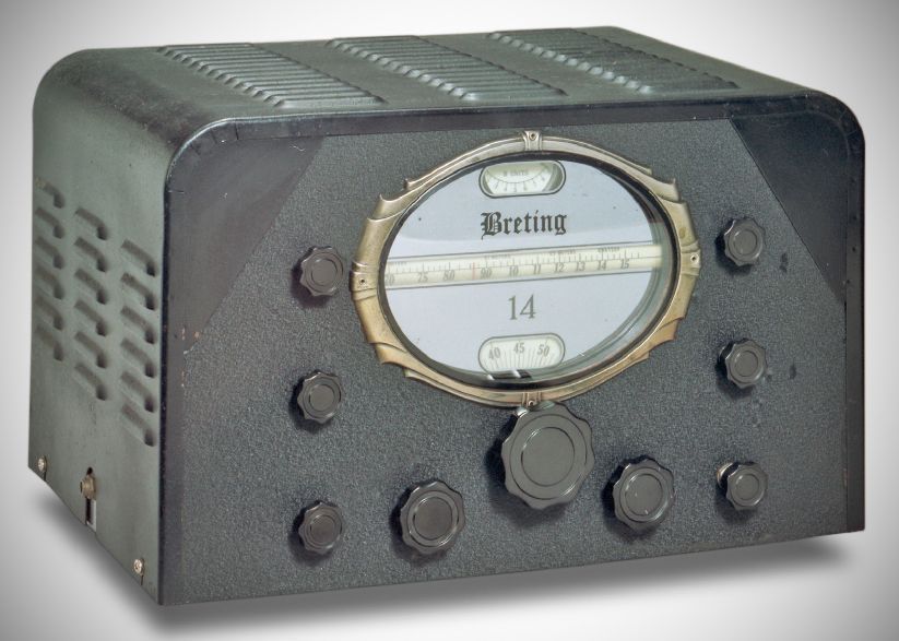
The Breting 14 is a rare, 1930s-era communications receiver manufactured by the Breting Radio Manufacturing Company of Los Angeles, California. Introduced as a high-end option for shortwave listeners and amateur radio operators, it is known for its striking aesthetics but non-standard and eccentric engineering, it is considered both a formidable restoration project and a "hot" performer when properly adjusted.
The Breting 14 utilizes a 14-tube superheterodyne design featuring an IF of 432 kHz. It features an unusual circuit arrangement across its stages:
– RF Section: Two RF amplifier stages using 6K7 tubes (V1 and V2). However, V1 is uniquely wired to function only on band 4. On all other bands, the bandswitch bypasses V1 and connects the antenna directly to the secondary RF stage V2.
– Mixer & Oscillator: A 6J7 mixer and a separate 6J7 high-frequency oscillator .
– IF Section: Two stages of IF amplification using a 6K7 and a 6L7.
– Detector & Audio: A 6B8 detector/amplifier feeds the audio section, which terminates in a push-pull audio output stage using two 6F6 tubes and driven by a third 6F6. Note: Restorers often substitute these with 6K6 tubes to lower the current draw on the power transformer.
– Noise Silencer: Uses a 6K7 ANL amplifier and a 6H6 ANL diode. This is not a standard Lamb-type silencer.
– BFO & S-Meter: A dual-purpose 6J7 tube. When the BFO is switched off, this tube acts as a cathode-follower meter amplifier to amplify the AVC signal for the S-meter. Turning the BFO on grounds out the AVC line connection via a tricky 5kΩ series resistor arrangement, dropping the S-meter to zero and activating the oscillator.
– Rectifier: 5Z3
Because the Breting 14 was not mass-produced on a large commercial scale, individual units vary widely in mechanical construction and front-panel layout.
The original factory manuals and Riders Volume 8 (reference 8-1-2) contain severe errors. If wired exactly to the official schematic, the receiver will not function. For example, the original diagram completely omits the BFO/S-meter switching arrangement, the grounded bottom of the audio gain control, and a special switch on the noise limiter control that cuts heater power to $V_8$ and $V_9$ when the limiter is turned off.
The main tuning capacitor features two sections per stage but is mounted on very long mechanical standoffs. Because the oscillator stage is placed all the way at the back of the chassis—far from the front panel dial—this distance introduces significant tuning backlash.
Units have been found with at least three different factory-installed vernier drives (including belt-driven variants), while some units shipped with no vernier drive at all. Furthermore, Breting omitted any lettering or markings for the control functions on the front panel.
On most units, the BFO tuning capacitor and its "on" switch are mounted vertically under the chassis, requiring a user or restorer to look beneath the unit or utilize a protruding lever/wire to adjust it. On rare variants, it is mounted conventionally with a front-panel knob.
To save money on solder tie-points, factory assembly regularly utilized unused, blank pins on tube sockets as tie-points, or simply soldered components together in mid-air.