Note
73, Nov 1967, p. 112. (new product announcement)
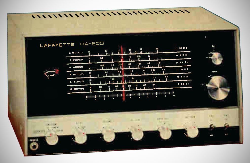
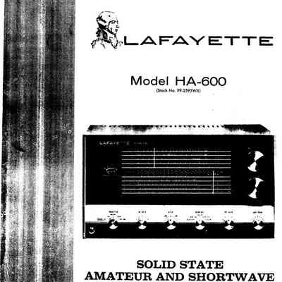
The Lafayette HA-600 is a solid-state, multi-band superheterodyne receiver designed for amateur radio operators and shortwave listeners. It covers from 150 kHz to 30 MHz in five bands.
The HA-600A included some minor circuit changes and added a couple of transistors, but the specifications remained unchanged.
Features
– Tuned RF Stage & Antenna Trimmer: Features a tuned RF amplifier and mixer stage along with a front-panel `ANT TRIM` control to match 50–400 Omega unbalanced antenna inputs.
– BFO & Product Detector: Variable Beat Frequency Oscillator (`BFO`) with pitch adjustment and marked Lower/Upper Sideband (LSB/USB) tuning indicators.
– Noise Control & Metering: Built-in AM Automatic Noise Limiter (`ANL`), full-time AVC circuit, separate `RF GAIN` and `AF GAIN` controls, and an illuminated S-meter.
– Power Supply Flexibility: Integrated universal power supply operating on either 105–120 V AC (50/60 Hz) or 12 V DC (negative ground). A rear-panel `PILOT` switch allows dial lamps to be switched off during 12 V DC operation to conserve current.
-Specifications
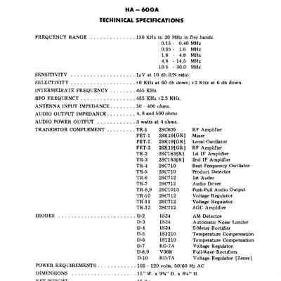
– Frequency Coverage: 150 kHz to 30 MHz across 5 selectable bands:
1. 0.15 – 0.40 MHz
2. 0.55 – 1.6 MHz
3. 1.6 – 4.8 MHz
4. 4.8 – 14.5 MHz
5. 10.5 – 30.0 MHz
– Modes of Operation: AM (phone), CW (code), and SSB (single sideband).
– Tuning System: Dual tuning dials featuring a main illuminated slide-rule dial alongside a calibrated bandspread dial for the 80, 40, 20, 15, and 10-meter amateur bands (plus a 0–100 logging scale).
– IF: Intermediate Frequency of 455 kHz utilizing a mechanical filter.
– Selectivity is rated at ±2 kHz at 6 dB down and ±6 kHz at 60 dB down.
– Sensitivity: 1 mV at 10 dB S/N ratio.
Transistors & FETs (HA-600)
– TR1: 2SC784 (RF Amplifier)
– FET1: T1712A (Mixer)
– FET2: T1712A (Local Oscillator)
– TR2: 2SCF11 (1st IF Amplifier)
– TR3: 2SCF11 (2nd IF Amplifier)
– TR4: 2SCF11 (Beat Frequency Oscillator)
– TR5: 2SCF11 (Product Detector)
– TR6: 2SDF1 (1st Audio)
– TR7: 2SBF1 (Audio Driver)
– TR8: 2SBF5 (PushPull Audio Output)
– TR9: 2SBF5 (PushPull Audio Output)
– TR10: 2SDF11 (Voltage Regulator)
Diodes
– D1: FV23 (RF Overload Protector)
– D2: 1S446 (AM Detector)
– D3: 1S446 (Automatic Noise Limiter)
– D4: 1S446 (SMeter Rectifier)
– D5: RD9A (Voltage Regulator)
– D6: RD11A (Voltage Regulator)
– D7: DS1P ( Power Supply Rectifier)
– D8: DS1P (Power Supply Rectifier)
Rear Panel Connections
– Audio Output: Terminals for 4 ohm, 8 ohm, and 500 ohm speaker outputs, delivering up to 3 W audio power output.
– Headphone & Tape Jacks: Standard 1/4'' front headphone jack (which automatically mutes the main speaker) and a rear RCA `TAPE REC` output jack.
– Remote Socket: An octal socket for transmitter switching, receiver muting, or standby control via an internal jumper plug.
Power Requirements: 105–120 VAC, 50/60 Hz, or 12 V DC (negative ground).
References
Brief description. Popular Electronics, Nov 1972, p. 29.