Note
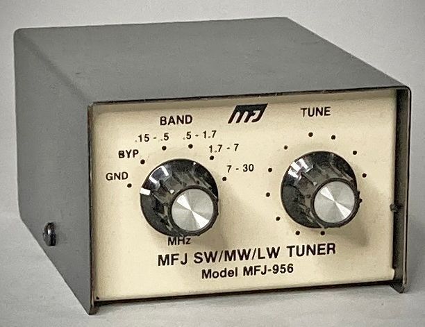
The MFJ-956 is a "passive preselector." It covers 150 kHz to 30 MHz across five bands. It was designed specifically as a receive-only device to help sub-compact or older receivers handle strong out-of-band signals and reduce "ghost" images on the dial.
While its predecessor (the MFJ-950) was a more complex active tuner, the 956 was specifically engineered to be a simplified, passive alternative that didn't require a battery or external power, making it a "buy it and forget it" accessory for shortwave listeners. The new (in 1988) crop of digital portable radios (like the Sony ICF-2010 and Sangean units) were notorious for "overloading" when connected to large outdoor antennas. The MFJ-956 was MFJ's budget-friendly solution to "clean up" those signals without needing the power required for an active preselector.
The 956 was one of MFJ’s longest-running products. While most MFJ tuner models (like the 941 or 949 series) went through several letter designations (A, B, C, D, E), the MFJ-956 has never had a letter suffix because the passive design remained unchanged for nearly 40 years.
The "0.15–30 MHz" range was a bit optimistic. Users often noted it performed best between 150 kHz and 15 MHz. Above that, the Q of the small inductors dropped significantly, making it less effective on higher frequencies.
Type: Passive LC Series Resonant Circuit.
The circuit uses a single-section air variable capacitor (365 pF) for the "TUNE" control together with a bank of selectable fixed inductors mounted directly to the band-switch. Unlike higher-end tuners with air-wound coils, these were typically molded or "green-bean" style inductors chosen for their compact size.
Switching: A 6-position rotary switch providing:
4 Frequency Bands: (VLF/LW, MW/BCB, and two SW bands).
Bypass: Connects antenna directly to the receiver.
Ground: Shorts the receiver input to ground (static protection).
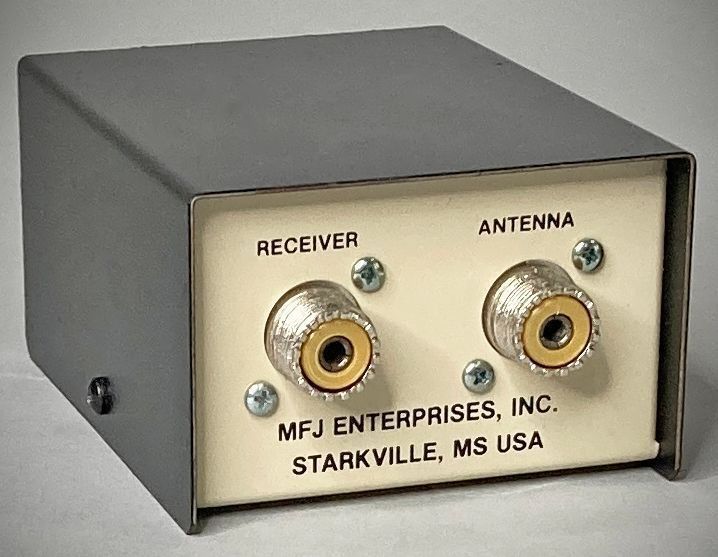
Connectors: Dual SO-239 (UHF female) jacks. In 1988, these were almost always riveted, not screwed.