Note
The Ten-Tec Model 418 is a 100-watt solid-state silicon MOSFET linear amplifier designed for amateur radio operations. It features both automatic and manual controls, offering ease of use across the 160- through 6-meter ham bands.
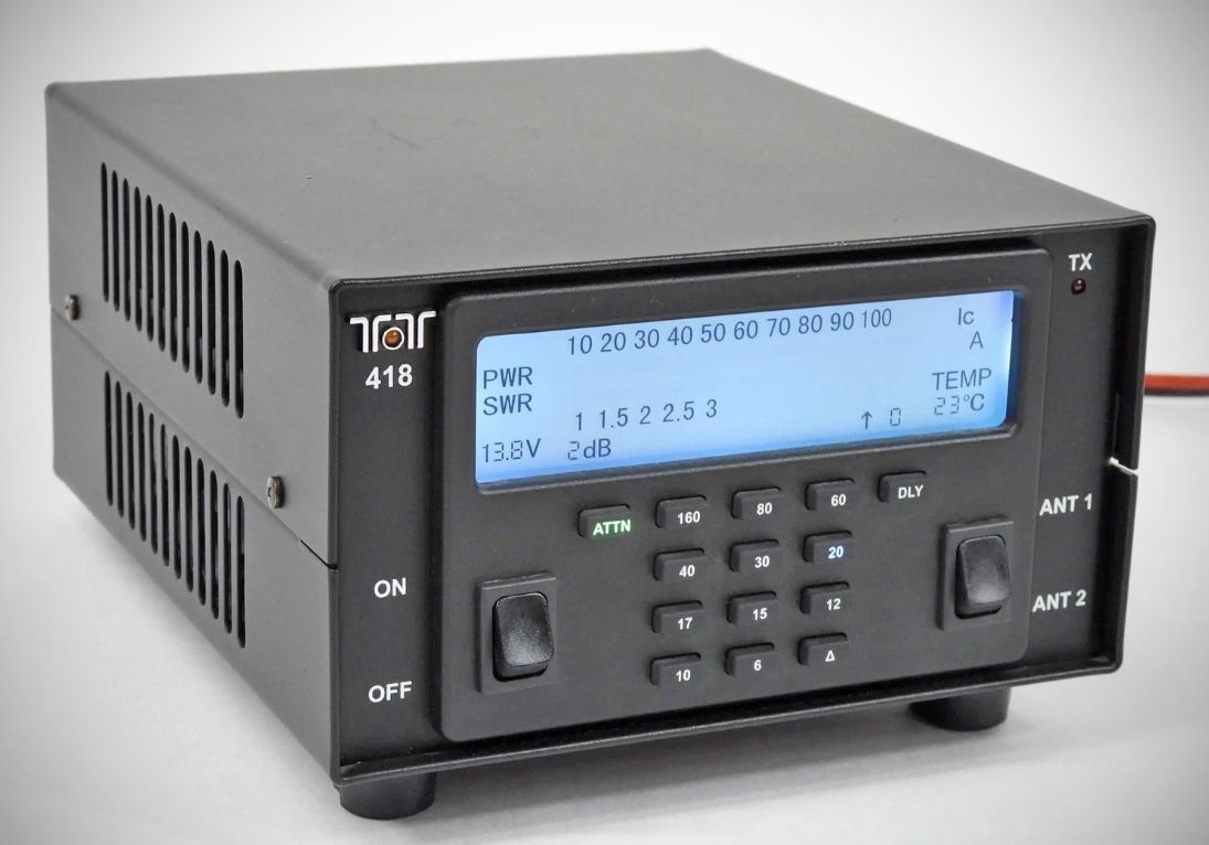
The 418 utilizes silicon MOSFET finals to achieve its 100W output power (+/- 1 dB). Its design incorporates an internal PIC processor running custom firmware to monitor frequency, RF input power, SWR, current draw, and heat sink temperature.
Features
Automatic Band Selection: While users can manually select bands using individual front-panel buttons, the 418 includes a frequency counter. If an RF input signal of 200 milliwatts or more is detected, it will automatically select the correct operating band.
Cooling & Duty Cycle: Thermal regulation is handled by two internal, temperature-controlled fans. It supports a continuous duty cycle at full 100W output for CW and SSB modes, and a 50% duty cycle (Tx/Rx) at 100W for AM, FM, AFSK, and PSK modes.
Display: It features a custom FSTN monochrome LCD display that shows a 10-to-100 watt bar graph for forward power (with a hanging peak dot indicator) and a 1-to-3 SWR bar graph. The display also shows real-time MOSFET final current ($I_c$), heat sink temperature (TEMP), attenuation settings, and warning indicators like OVERDRIVE or FAULT.
Backlight Customization: The display is backlit by 6 LEDs (2 red, 2 blue, 2 green). Users can customize the color intensity and overall brightness directly through specific button key-press combinations.
Attenuator (ATTN): Designed to reduce incoming power if a transceiver cannot dial down to 5 watts or less. It offers selectable steps of 0, 2, 4, or 6 dB of attenuation, which can also be utilized to purposefully drop the total output below 100 watts.
Delay (DLY): Adjusts the transition delay from transmit back to receive, which helps keep the amplifier engaged longer during CW keying to avoid constant relay clicking.
Delta Button: When illuminated, it forces the amplifier to look for band selection data streaming from the rear accessory port (such as when interfaced directly with a companion rig like the Ten-Tec 539 Argonaut VI).
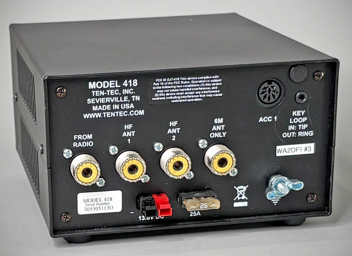
Antenna Switching: The rear panel contains four SO-239 connectors: one designated for the incoming transceiver signal (RADIO) , two selectable HF antenna ports (HF ANT 1 and HF ANT 2) , and a dedicated 6M ANT port. In its default state, the amplifier automatically routes 6-meter operation to the 6M connector, though firmware updates allow users to bypass this and use ANT 1 or 2 instead.
Key In / Key Out: Equipped with a 1/8" (3.5mm) stereo jack where the tip acts as the key input, and the ring functions as a key output. The key output utilizes a transistor switch (rather than a mechanical relay) with a built-in 4-millisecond delay to avoid hot switching.
Accessory Port (ACC 1): An 8-pin DIN connector that handles grounding, clock/data stream interface lines, and auxiliary keying.
Power Connection: Heavy-duty Anderson Power Pole connectors (rated at 30 amps).
Operational Protection & Fault Handling
The 418 acts protectively to prevent catastrophic failures of its internal components. When a critical constraint is breached, it trips into a "FAULT" state, bypasses the amplifier path entirely, and states the reason on the display. Fault protection parameters include:
– Overcurrent Protection ($I_c$): Drops power if current draw clears 30 amps.
– Thermal Protection: Trips if the heat sink rises to 85°C.
– Overdrive Protections: Triggers if the input power clears 10 watts or if total forward output power surges over 115 watts.
– SWR Protection: Activates if the SWR rises above 3.5:1 (monitored whenever output exceeds 50 watts).
– Hot-Switching Safeguard: If the key down signal line drops while RF output is actively pulsing through the circuit, the unit holds the transmit state until the RF vanishes, saving the T/R relays from burning up.
Specifications
– Power – Output: 100 W, +/- 1 dB
– Duty Cycle (SSB, CW): continuous service @ 100W
– Duty Cycle (AM, FM, AFSK, PSK): continuous service @100W, 50% duty cycle (Tx/Rx)
– Frequency Range: 160-6 meters.
– Antenna Impedance: 50 ohms nominal. Antenna Connectors: 4 x SO-239
– Operating Temp. Range: 0-50 degrees Celsius
– Key Jack: 1/8 “ Stereo Tip-Key in Ring- Key out
– ACC Din Connector: 8 PIN DIN Connector ; Aux Key,Clock/Data/ Enable, Ground
– DC Power Connector: Power Poles Fuse: Automotive Blade Style Fuse, 25 Amp 32 volt
– Display: Custom FSTN monochrome LCD Display Backlight: 6 LEDS RF
– Cooling: 2 internal fans temperature controlled
– Harmonic & Spurious Outputs:
-50dBc typical@100 W HF
> -60dB @ 6 METERS
– Third Order Intermod: 30dB below peak All measurements are typical. Results will vary based on different Test Environment,
Power requirements: 13.8V +/-15% , approximately 17 amps during transmit and requires a well-regulated power supply capable of delivering 23 amps continuous duty. Has an automotive-style 25-amp blade fuse.