Note
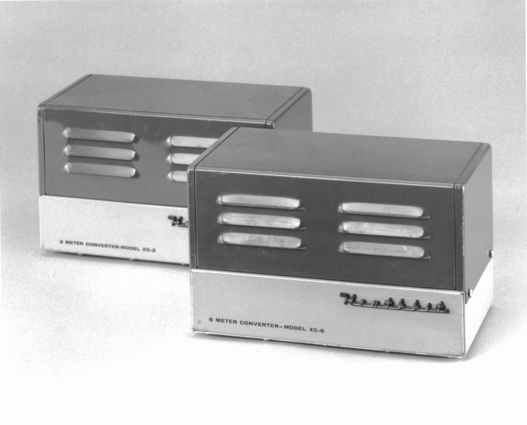
XC-2 1959-1960 $36.95
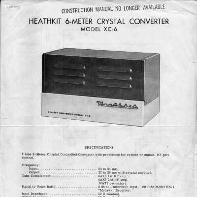
XC-6 1959-1960 $26.95
It’s s hard to say exactly why these units lasted only one year or so. They worked well enough and were eminently affordable. The most likely explanation is that they were supplanted by the HW-10 Shawnee (six meter) and HW-20 Pawnee (two meter) transceivers, both released in 1961. In any case, they did not last long and are fairly rare as a result.
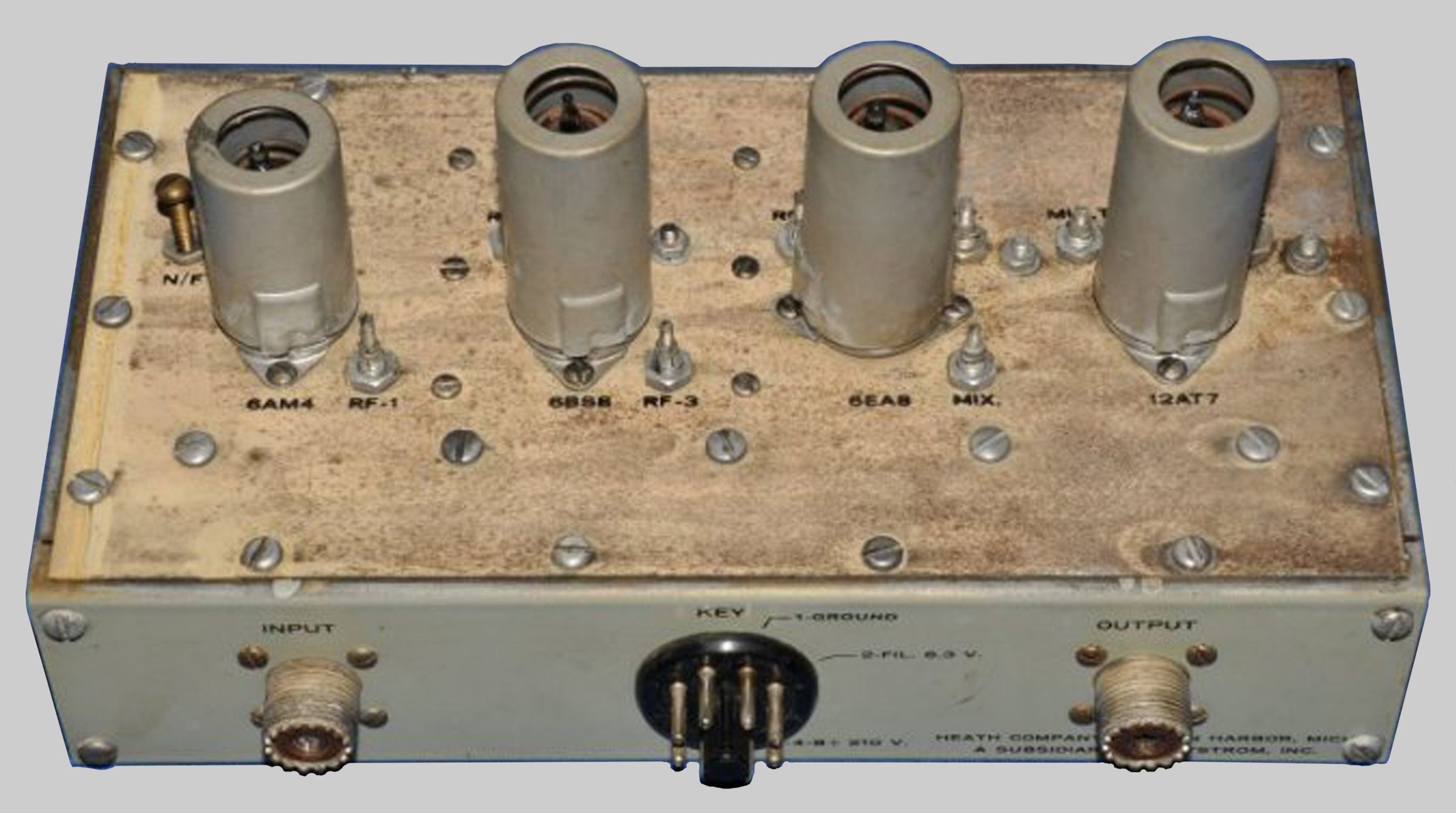
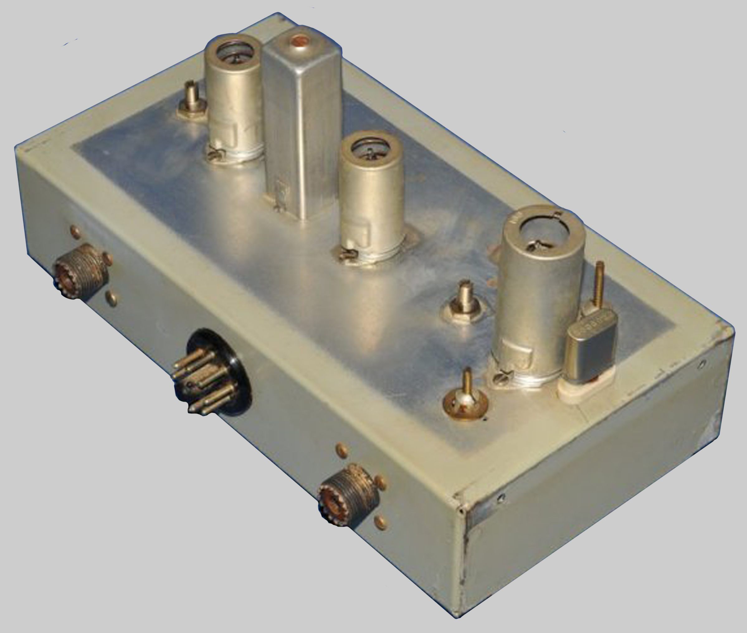
Although the units work on the same principle, they employ circuits that are very different. The details of the differences are beyond the scope of this book. The four tube XC-2 consists of two RF amplifier stages, a triode mixer stage, an IF amplifier stage, and a crystal controlled oscillator. The three tube XC-6 consists of two RF amplifier stages, an oscillator, and a mixer. Basic specifications for both units are essentially the same.
The XC-2 covers from 144-148 MHz, and the XC-6 covers from 50-54 MHz. The units were supplied with a 0.005% 3rd overtone crystal that provided output from 22-26 MHz. This matched up with a special band provided on the RX-1, for which these converters were specifically designed. By changing the crystal frequency, the output could be shifted to accommodate use of the converters with other receivers.
Power for the units is provided by the RX-1. If the converters are used with a different receiver a source of power must be provided. Refer to the specifications for power requirements. Note that for use with the RX-1, a 1000Ω, 7 watt dropping resistor must be used to lower the 210 VDC from the receiver to the 150 VDC required by the converter. Refer to Figure 4 for the location of the dropping resistor.
Note: If your RX-1 tuner assembly (#100-139) has a serial number less than 725 a realignment of the tuner is required. The XC-2/6 manual covers this procedure.
Alignment requires a sweep generator, an RF signal generator and an oscilloscope.
There are no controls on the converters. The rear panel contains a pair of SO-239 connectors for input and output, and a octal plug for power connections. The front panel is adorned with a “3D” silver plastic molded “Heathkit” script-type logo, the same as used in the RX-1 et al. Chassis and shields are silver plated. Two-tone green paint matches RX-1.
References:
Review (XC-6). QST. Oct 1959, p. 41.
Brief description. Electronics World, Dec 1959, p. 130.
Review. Popular Electronics, Jan 1960, p. 65.
Review (XC-2). QST. Sep 1960, p. 47.
Frequency input:
XC-2: 144 to 148 MHz
XC-6: 50 to 54 MHz
Frequency output:
XC-2: 22 to 26 MHz. May be tuned as high as 35 MHz with appropriate crystal
XC-6: 22 to 26 MHz. May be tuned to 14 to 18 MHz without modification
Crystal:
XC-2: 61 MHz ±0.005%, 3rd overtone
XC-6: 28 MHz ±0.005%, 3rd overtone
Noise figure:
XC-2: 1.0 µV provides 20 db of thermal quieting
XC-6: not provided
Signal to noise ratio:
XC-2: not provided
XC-6: 8 db at 1.0 µV input (with RX-1)
Sensitivity:
XC-2: approximately 0.1 µV will provide a signal better than 6.0 db over noise level when used with a 5 kHz bandwidth filter.
XC-6: not provided
Pass band:
XC-2: essentially flat from 144 to 148 MHz. About 35 db down at 143 and 149 MHz. May be peaked to favor any portion of the band
XC-6: any two megahertz segment between 50 and 54 MHz
Input/output impedance: 50 to 75Ω
Power requirements:
XC-2: 150 VDC at 50 mA, 6.3 VAC at 1.375 amps*
XC-6: 150 VDC at 50 mA, 6.3 VAC at 0.65 amps*
*requires a 1000Ω, 7 watt dropping resistor for use with RX-1
Tubes:
XC-2: (1) 6AM4, (1) 6BS8, (1) 6EA8, (1) 12AT7
XC-6: (2) 6AK5, (1) 12AT7
Photos, general information and specifications from "Heathkit: A Guide to the Amateur Radio Products," by Chuck Penson, WA7ZZE. Used with permission.