Note
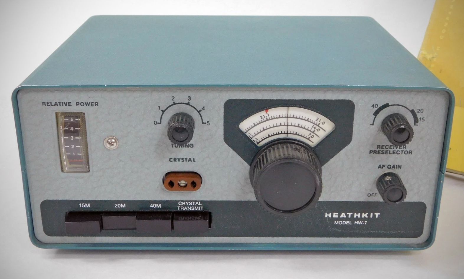
The HW-7 was the first of three very successful QRP transceivers. The HW-7 covers the CW portions of the 40, 20, and 15-meter band and features VFO or crystal-controlled operation and push button selection of band.
The HW-7 has a rated RF input power of 3 watts on 40, 2.5 watts on 20, and 2 watts on 15 meters. The receiver is a direct conversion type using a dual-gate MOSFET product detector as a front end, with a single tuned circuit. Receiver selectivity is determined by an m-derived low-pass audio filter in the audio line between the product detector and the AF amp. Selectivity is about 2 kHz with broad skirts. Sensitivity is better than 1.0 µV. There is no internal speaker.
The HW-7 is not a QSK transceiver. The receiver is muted during transmit periods with an adjustable delay T/R relay.
Front panel controls include PA tuning, receiver preselector, main tuning (6:1 tuning drive ratio), AF gain, and push buttons for band and VFO/crystal selection.
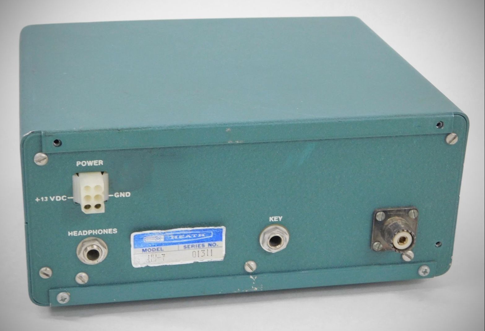
There are rear panel connections for 12 VDC, standard quarter-inch jacks for a key and headphones (there is no built-in speaker), and an RCA jack for a 50Ω (not 75Ω) antenna. The meter reads relative power only.
The HW-7 is not without its problems. The receiver is very microphonic, and early units suffered from more than a little cross-modulation (a problem Heath later fixed). In addition, when used with an AC power supply and an end fed wire (even with a transmatch) a 60 Hz hum may be noticed in the receiver. This is not a problem when running on batteries, of course. Some chirping and clicking are common especially on 15 and 20-meters. One minor complaint—the sidetone is very loud, causing the operator to have to lower the audio gain during transmit and raise it during receive. Also, since direct conversion receivers do not provide single-signal reception, care must be taken to adjust the receiver correctly so that the transmitter signal may be heard by the station being worked. The station being worked must be tuned in on the high frequency side of its zero beat frequency. This is necessary because of the way the HW-7’s transmitter offset has been designed.
MODIFICATION FOR USE WITH HD-1410
The HW-7 was designed to be compatible with the HD-10 electronic keyer. To use the rig with the HD-1410 electronic keyer two small changes are required.
First, the two wires going to the HW-7’s key jack must be reversed. Second, R39 must be changed from 470Ω to 4700Ω.
Dozens, perhaps hundreds, of modifications have been published for HW-7. In spite of any shortcomings, the HW-7 was very popular and sold well. Also see HWA-7-1 matching power supply. Two-tone green color matches other HW series gear.
References:
Review. QST. Jan 1973, p. 48.
Review. CQ. Apr 1973, p. 60.
Preselector mod. QST. May 1973, p. 42.
RIT for. QST. Jun 1973, p. 48.
New front end for. QST. Dec 1973, p. 23.
Modification. QST. Jan 1974, p. 35.
Modification (correction). QST. Mar 1974, p. 83.
Modifications. Ham Radio. Dec 1974, p. 60.
RIT for. QST. Jul 1975, p. 38.
Slippers (a small amplifier for). QST. Dec 1975, p. 45.
Hum reduction. QST. Jul 1976, p. 42.
Sidetone level control. QST. Nov 1976, p. 41.
Autotune (“touch tuning”) circuit for. Ham Radio. Nov 1979, p. 81.
Frequency coverage: 7.0 to 7.2, 14.0 to 14.2 and 21.0 to 21.3
DC input power: 3 watts on 40 meters, 2.5 watts on 20 meters, 2 watts on 15 meters
Frequency control: VFO or crystal
Output impedance: 50Ω
Sidetone: built-in
Spurious and harmonic levels: at least 25 db down
Sensitivity: 1 kHz @ 6 db down
Mode: CW only
Audio output impedance: 1000Ω
Frequency stability: less than 100 Hz drift after 10 minutes warmup
Power requirements: 13 VDC @ 35 mA receive, 450 mA transmit
Solid State:
diodes: (2) 1N191, (1) VR36A zener
transistors: (1) 40673, (2) 2N3393, (2) X29A829, (1) S2091, (2) MPF105, (2) MPS6521, (2) MPSU05
integrated circuit: CA3035V1
Photos, general information and specifications from "Heathkit: A Guide to the Amateur Radio Products," by Chuck Penson, WA7ZZE. Used with permission.