Note
The GR-54 was released about six months after the GR-64 and was the last of the “GR” family of receivers. The 54 was Heath’s top-of-the-line slide-rule dial type receiver and the best tube-type receiver of the series.
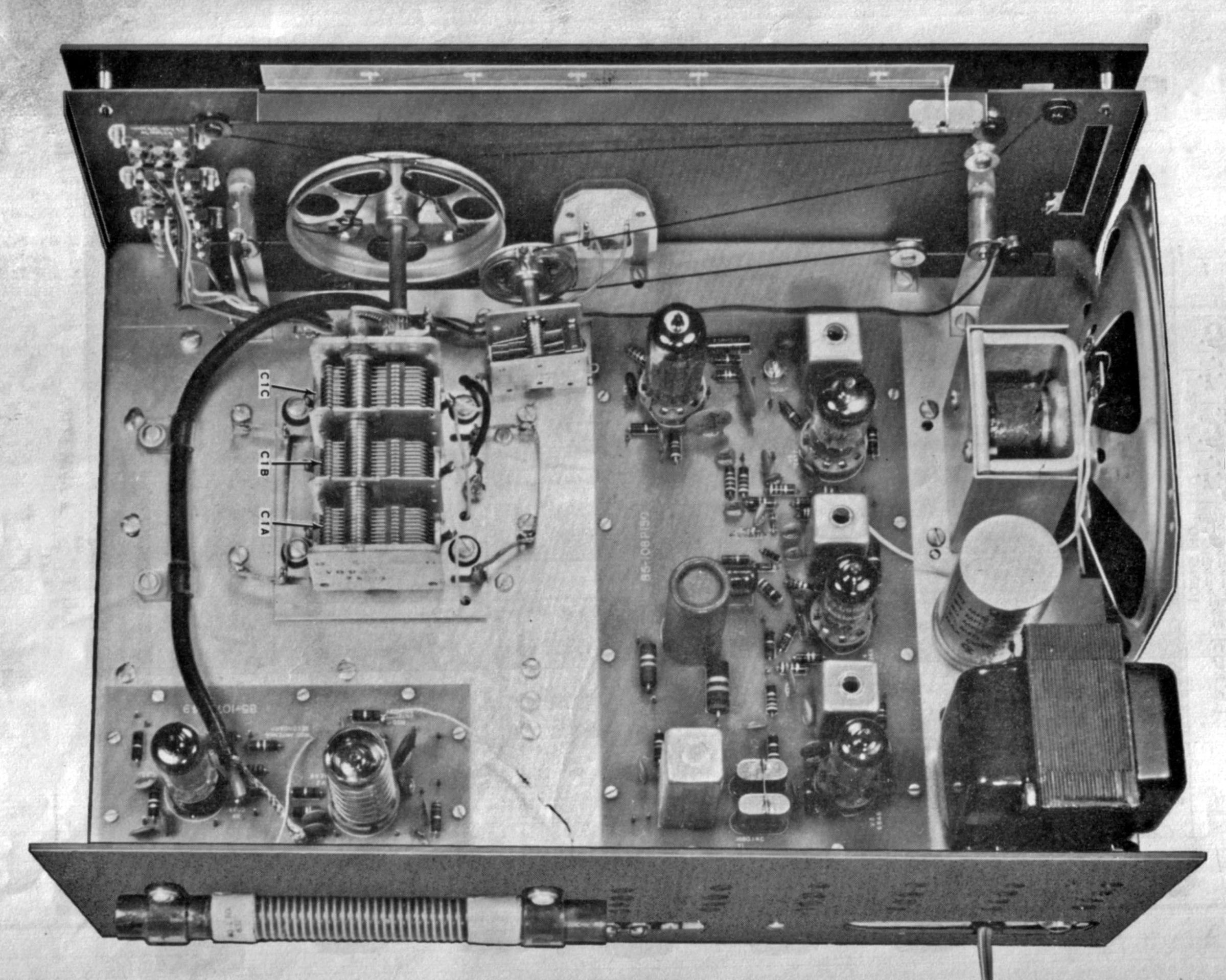
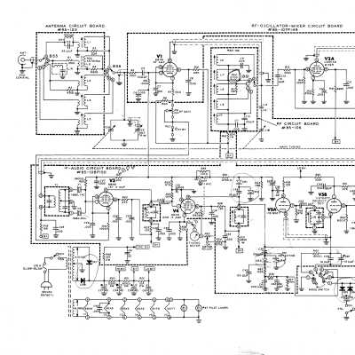
The receiver employs a superheterodyne design using six tubes and six diodes (not including the power supply), and is built on five PC boards, two on the chassis top and three below in the band switching circuit. Frequency coverage is from 180 to 420 kHz, from 550 to 1550 kHz, and from 2 to 30 MHz in 5 bands, with an intermediate frequency of 1682 kHz. This IF makes the GR-54 incompatible with Heath Q-multipliers including the QF-1, HD-11, and GD-125.
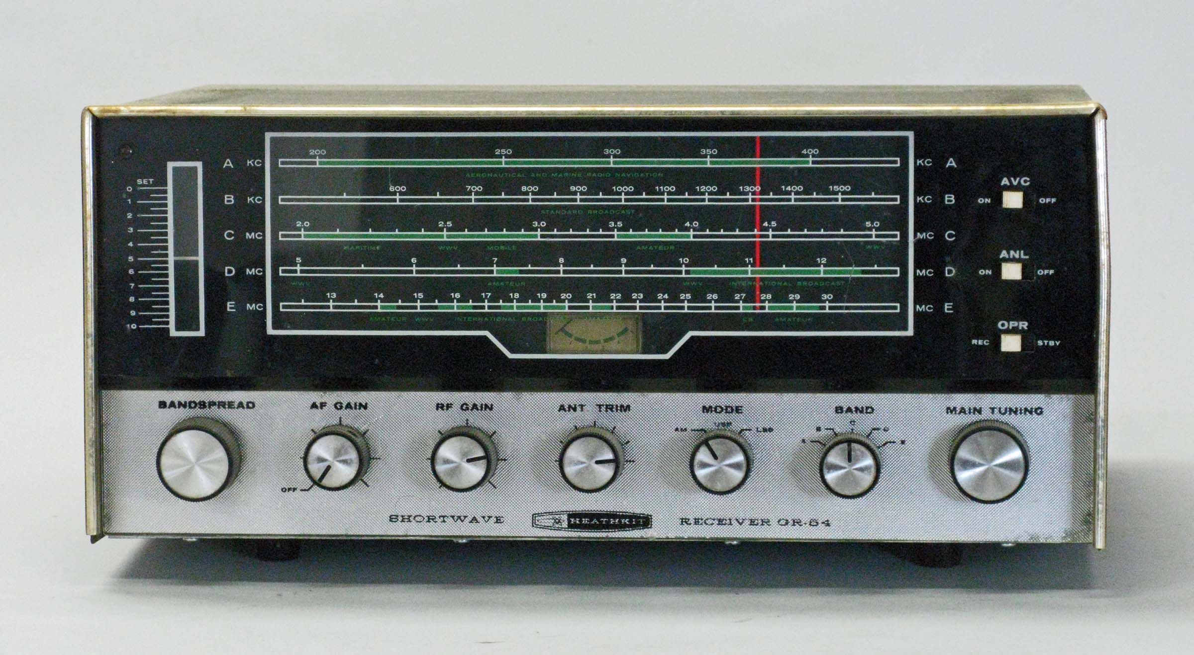
The GR-54 is equipped with a variety of features including a tuned RF-stage, a separate product detector for SSB/CW reception; switchable upper/lower sideband; an S-meter; an electrical bandspread; a lighted dial face; and a solid-state transformer-type power supply.
Selectivity is enhanced with a crystal filter rated for 3 kHz minimum at –6 db and 7.5 kHz maximum at –20 db. Depending on the band, the sensitivity varies from as high as 1.0 µV to as low as 8.0 µV. This kind of sensitivity is typical of the genre.
Stability was also typical of the genre, meaning that the GR-54 is subject to a bit of drift almost no matter how long it has been warmed up.
Additional features of the receiver are an ANL, an AVC, an antenna trimmer control, a built-in ferrite rod antenna for broadcast band reception, a built-in 4x6 speaker, a headphone jack, and a built-in code practice oscillator and code key jack. To practice code, tune in a weak AM station with the BFO turned on. The resulting heterodyne can be used as the tone source and can be keyed from the rear panel CW key terminals. Note: for normal operation, the CW key terminals must be shorted.
Unlike the GR-64, signals on Band B (the AM broadcast band) are provided by the ferrite stick antenna OR whatever antenna is connected to the antenna terminals. A rear panel RCA type antenna connector will accommodate unbalanced antennas from 30 to 75Ω. A ground wire may be attached to the right-hand terminal of the CW key terminal strip.
Early versions were designed for 120 VAC only. Later versions could be wired for either 120 or 240 VAC.
The GR-54 can be aligned with or without a VTVM. The receiver is housed in a gray cabinet and has white-and-green band markings.
Caution: The plastic front panel cracks easily.
The GR-54 was replaced in 1971 by the solid state SW-717 which was, in terms of features, closer to the GR-64.
References
Review. 73 Amateur Radio. Nov. 1966, p. 78.
Frequency coverage:
band A: 180 to 420 kHz
band B: 550 to 1550 kHz
band C: 2.0 to 5.0 MHz
band D: 5.0 to 12.5 MHz
band E: 12.5 to 30 MHz
Image rejection:
Low end High end
band A: 95 db or more 80 db or more
band B: 60 db or more 25 db or more
band C: 50 db or more 45 db or more
band D: 50 db or more 35 db or more
band E: 45 db or more 15 db or more
IF: 1682 kHz
Selectivity (for 10 db (S+N)/N):
3.0 kHz minimum @ 6 db
7.5 kHz minimum @ 20 db
Sensitivity:
AM SSB/CW
band A: 1.6 µV 0.7 µV
band B: 8.0 µV ———
band C: 1.0 µV 0.4 µV
band D: 1.2 µV 0.5 µV
band E: 6.0 µV 4.0 µV
Antenna input impedance: 30 to 75Ω
Audio output impedance: 8Ω
Power requirements: 120/240 VAC, 50/60 Hz, 45 watts
Tubes: (2) 6BA6, (1) 6BH6, (1) 6EA8, (1) 6HF8, (1) 12AT7
Photos, general information and specifications from "Heathkit: A Guide to the Amateur Radio Products," by Chuck Penson, WA7ZZE. Used with permission.