Note
Introduced for Christmas in 1965, the SB-100 was the first of several enormously popular transceivers that included the SB-101 and SB-102. Patterned after the Collins KWM-2, the SB series of transceivers were among the most popular ever made by any manufacturer. Indeed, for a while in the late 60s it seemed as though every other person you heard on the air was running a “Sugar Baker” rig.
Interestingly, the SB-100 was first seen in an ad in 73 magazine in October 1963, page 19. The ad was for the SB-300 receiver, but included smaller images of the SB-100, SB-200 and SB-400 with the text “Watch for these new Heathkit releases.” The SB-100 didn’t show up in the Heath catalog until October 1965 (two full years after the 73 sneak peek), and did not appear in QST magazine until December.
The following is both a specific discussion of the SB-100 and a general discussion of the SB-101 and 102—there are many similarities. For a specific discussion of the differences in the 101 and 102, see listings for those products.
The SB-100 uses 20 tubes including a pair of 6146 beam power tubes in the final amp and is built on nine PC boards including five main boards and four smaller “switchboards” used in the band switching assembly. The SB-100 covers 500 kHz portions of the 80-10 meter bands. The 10 meter band is covered in four 500 kHz segments.
The transceiver operates USB, LSB, or CW, with no provision for AM. Transmitter input power is 180 PEP and 170 CW. RF output power is around 100 watts (80 watts on 10 meters). The receiver is a dual conversion superheterodyne type with an IF of 3395 kHz. Both transmitter and receiver use a 6 pole crystal lattice filter.
Selectivity is 2.1 kHz at 6 dB down. Receiver sensitivity is rated at 1.0 µV (better in the 101 and 102). Drift is less than 100 Hz per hour after a 20-minute warm-up.
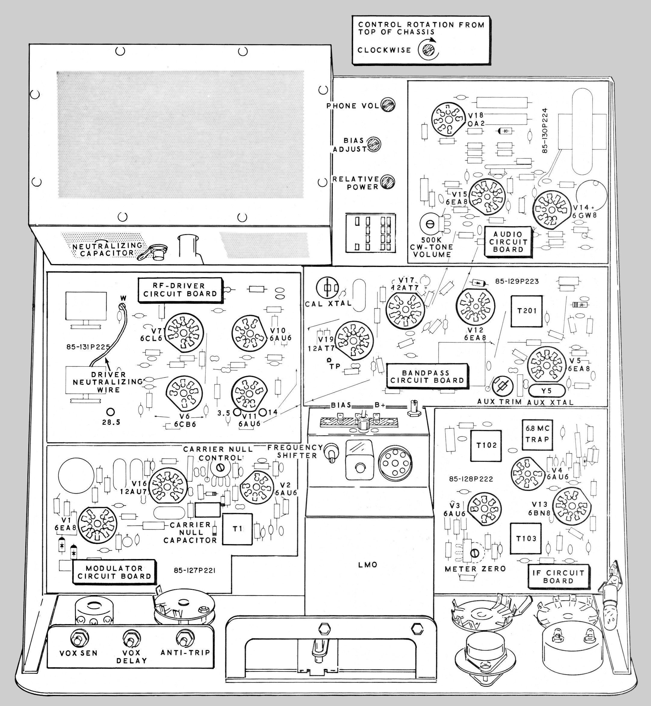
The SB-100 uses a custom designed VFO Heath called the “LMO” or Linear Master Oscillator. The LMO is pre-assembled and aligned and housed in a sealed box, and came with a stern warning not to open it. The LMO is a true “black box.” It is shown on the schematic as an empty box, and its vacuum tube (a 6BZ6, also not shown on the schematic) does not have a “V” number designation. LMOs were made for Heath by several subcontractors including TRW and were both complicated and expensive to produce. Still, they were linear from one end of the band to the other and were far less expensive than the permeability tuned oscillators used by Collins.
The LMO is accurate to 400 Hz after calibration from the nearest 100 kHz point. The dial drive mechanism is relatively simple, has a good feel and good resetability, is reasonably free from backlash, and provides about 10 feet of band spread per megahertz.
Basic features include PTT and VOX operation, LMO or crystal controlled transceive (one crystal position, with trimmer), built-in T/R switching, and a built-in 100 kHz crystal calibrator.
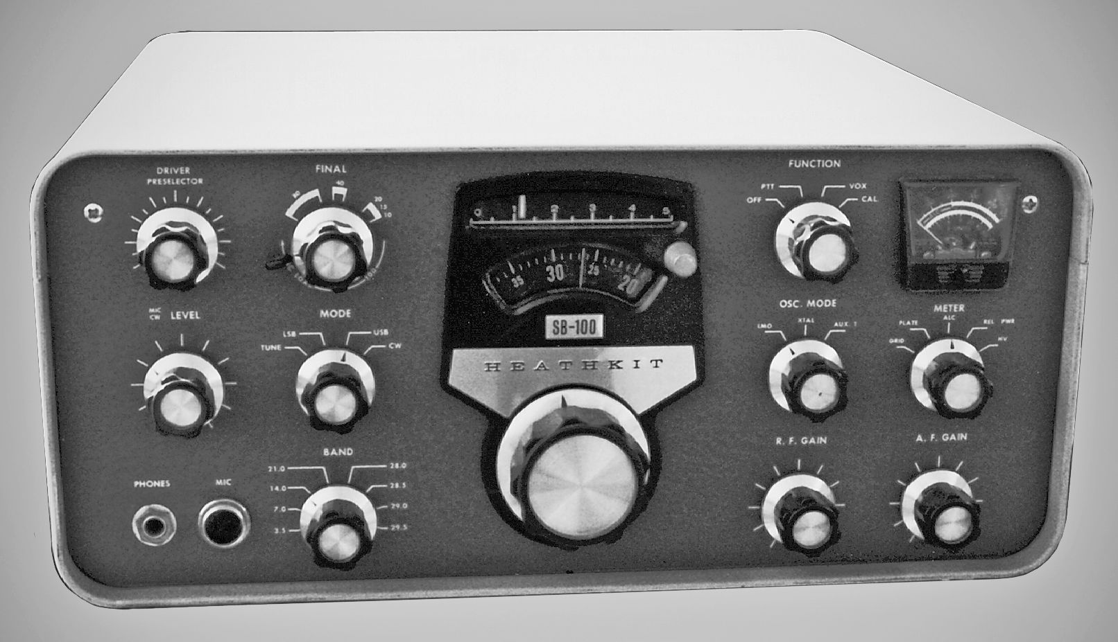
Front panel controls include main tuning, driver tuning and preselector, final tuning, final loading, mic and CW level, mode, band, function, frequency control (XTAL or LMO), meter function, RF gain, AF gain, and a dial calibration knob.
Although there was no provision for a CW filter, Heath later released an upgrade kit that added the ability to switch between two filters, SSB or CW. In addition to the filter, the kit included a concentric switch control and associated lever-arm, as well as a small plate with new dial markings for the front panel. Refer to Figures 1 and 2. The lever-arm and dial plate make this upgrade easy to spot.
The illuminated meter reads ALC/S-units, relative power, high voltage, grid current, and plate current. Internal controls include VOX sensitivity, delay and anti-trip, carrier null (control and capacitor), meter zero, CW sidetone level, relative power meter adjust, PA bias, headphone gain, and neutralizing.
Rear panel connections include quarter-inch key jack and RCA connectors for an 8Ω speaker, 600Ω output, phone patch input, ALC input, RF output, and receiver antenna input. There is also an 11 pin plug for power input and an antenna selector switch to select a separate or common antenna for transmit and receive.
Many of these rigs have been user modified and fitted with an SO-239 to replace the RCA RF output connector. Other acceptable modifications include the installation of jacks needed to operate the SB-650 frequency display and the addition (or use) of spare jacks to support the SB-610 and/or SB-620.
Units with other modifications should be avoided except for parts. Note: Because of mechanical changes in the SB-102’s solid state LMO, it is not possible to retrofit an SB-100 or 101 with an LMO from a 102.
The SB-100 series of transceivers has no built-in power supply and is designed for use with the HP-13 (mobile) and HP-23 (fixed) series power supplies.
The SB series of products all use a two-tone green wrinkle paint scheme. The paint color and texture varied from batch to batch and from year to year, so finding two SB units of the exact same paint shade and texture may not be easy.
References:
Review. Popular Electronics, Jun 1966, p. 85.
Review. 73 Amateur Radio. Aug. 1966, p.50.
Review. QST. Sep 1966, p. 45.
Review (more on). QST. Dec 1966, p. 77.
Low voltage equalization. QST. Dec 1966, p. 49.
Adding RIT. QST. May 1967, p. 49.
Adding RIT. Ham Radio. Aug 1976, p. 81.
AGC modification. QST. Nov 1967, p. 50.
Improvements. QST. May 1968, p. 53.
Upgrading. CQ. Aug 1968, p. 73.
Preselector improvement. QST. Nov 1968, p. 50.
WWV reception. QST. Apr 1969, p. 47.
WWV reception. Ham Radio. Jan 1977, p. 78.
Better connection to SB-620. CQ. Feb 1970, p. 89.
External VFO for. QST. Oct 1970, p. 42.
External VFO for (more on). QST. Jan 1971, p. 45.
Narrow shift RTTY reception. Ham Radio. Oct 1971, p 64.
Narrow shift RTTY reception. Ham Radio. Jun 1973, p 54.
Improved AVC. CQ. Nov 1973, p. 10.
Hum. QST. Jun 1971, p. 40.
Hum / hot resistor. Ham Radio. Jun 1975, p. 59.
Hum / relay mods. Ham Radio. Jun 1976, p. 34.
Hum. CQ. Nov 1969, p. 90.
Hum reduction. QST. Aug 1976, p. 43.
Using an outboard receiver with. Ham Radio. Feb 1970, p. 68.
Fixing audio hum. QST. Jun 1971, p. 40.
Increase friction in worn zero set. QST. Jan 1973, p. 52.
Use with a separate receiver. Jan 1975 QST, p. 44.
OSCAR reception with. QST. Feb 1975, p. 46.
Speech processor. Ham Radio. Jun 1975, p. 38.
Digital display for. Ham Radio. Sep 1976, p. 16.
Heterodyne crystal switching. Ham Radio. Mar 1977, p. 78.
Underrated resistor / CW desense. Ham Radio. Mar 1977, p. 79.
Use with low impedance headphones. Ham Radio. Oct 1977, p. 87.
Excessive CW recovery delay. Ham Radio. Mar 1978, p. 110.
Better S/N and gain for. QST. Jun 1978, p. 44.
S-meter problem. QST. Apr 1978, p. 40.
Zero-set dial modification. QST. Feb 1980, p. 44.
Digital frequency display, Ham Radio. Jan 1987, p. 8.
Optimizing. QST. Feb 2003, p. 77.
General information. Electric Radio. Nov 2006.
General information. Electric Radio. Sep 2016.
Specifications apply to SB-100, SB-101 and SB-102. Specifications unique to the SB-101 and/or SB-102 are noted separately.
TRANSMITTER
DC power input:
SSB: 180 watts PEP (100% duty cycle)
CW: 170 watts (50% duty cycle)
RF power output: 100 watts on 80 to 15 meters; 80 watts on 10 meters
Output impedance: 50 to 75Ω with less than 2:1 SWR
Oscillator feedthrough or mixer products: 55 db below rated output
Harmonic radiation:
SB-100: 35 db below rated output
SB-101/102: 45 db below rated output
T/R operation:
SSB: PTT or VOX
CW: provided by operating the VOX from a keyed tone; grid block
CW side tone: internally generated; about 1000 Hz
Microphone input: high impedance, –45 to –55 db
Carrier suppression: 50 db down from single-tone output at 1000 Hz
Unwanted sideband suppression:
SB-100: not specified
SB-101/102: 55 db down from single tone output at 1000 Hz
Third order distortion: 30 db down from two-tone output
RF compression: 10 db or greater at 0.1 mA final grid current
RECEIVER
Sensitivity:
SB-100: less than 1.0 microvolt for 15 db signal+noise to noise (SSB)
SB-101: less than 0.5 microvolt for 10 db signal+noise to noise (SSB)
SB-102: less than 0.35 microvolt for 10 db signal+noise to noise (SSB)
SSB selectivity (3395 kHz filter):
2.1 kHz minimum for 6 db down
5 kHz maximum for 60 db down
2:1 nominal shape factor at 60:6 db
CW selectivity (optional): 400 Hz minimum at 6 db down; 2 kHz 60 db down
Input: low impedance for unbalanced coaxial input
Output impedance: 8Ω and 600Ω speaker, and high impedance headphone
Audio power output: 2 watts with less than 10% distortion
Spurious response: image and IF rejection better than 50 db; internal spurious signals below equivalent antenna inout of 1.0 microvolts
GENERAL
Frequency coverage (MHz): 3.4 to 4.0, 7.0 to 7.3, 14.0 to 14.5, 21.0 to 21.5, 28.0 to 28.5, 28.5 to 29.0, 29.0 to 29.5, 29.5 to 30.0
Frequency stability: less than 100 Hz drift per hour after 20 minute warmup from ambient conditions. Less that 100 Hz for 10% line voltage variations
Modes: USB, LSB (emission type A3a for SB-100, A3j for SB-101/102); CW (emission type A1)
IF: 3395 kHz
Visual dial accuracy: within 200 Hz on all bands
Electrical dial accuracy: with 400 Hz after calibration to nearest 100 kHz point
Dial mechanism backlash: less than 50 Hz
Calibration: 100 kHz crystal
Audio frequency response: 350 to 2450 Hz
Phone patch impedance: 8 or 600Ω receiver input to patch, high impedance patch input to transmitter
Power requirements:
700 to 800 VDC, 250 mA, 1% maximum ripple
300 VDC, 150 mA, 0.05% maximum ripple
–110 VDC, 10 mA, 0.5% maximum ripple
12 VDC or VAC, 4.76 amps
Size:
Tubes (SB-100): (1) 0A2, (5) 6AU6, (1) 6BN8, (1) 6BZ6, (1) 6CB6, (1) 6CL6, (4) 6EA8, (1) 6GW8, (2) 12AT7, (1) 12AU7, (2) 6146
Tubes (SB-101): (1) 0A2, (5) 6AU6, (1) 6BN8, (2) 6CB6, (1) 6CL6, (4) 6EA8, (1) 6GW8, (2) 12AT7, (1) 12AU7, (2) 6146
Tubes (SB-102): (1) 0A2, (1) 6HS6, (4) 6AU6, (1) 6BN8, (1) 6CB6, (1) 6CL6, (4) 6EA8, (1) 6GW8, (2) 12AT7, (1) 12AU7, (2) 6146
Notes on tube lineup: in the SB-101 the LMO was changed from a 6BZ6 to a 6CB6. In the SB-102, the RF amplifier (V10) was changed from a 6AU6 to a 6HS6, and the LMO was changed to solid state, deleting the 6CB6. In all versions use only 6146 final amplifiers, NOT 6146A, 6146B or 6146W.
Photos, general information and specifications from "Heathkit: A Guide to the Amateur Radio Products," by Chuck Penson, WA7ZZE. Used with permission.