Note
SA-2060 1981-1983 254.95
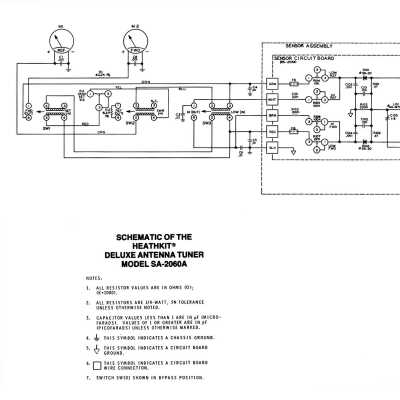
SA-2060A 1983-1991 279.95
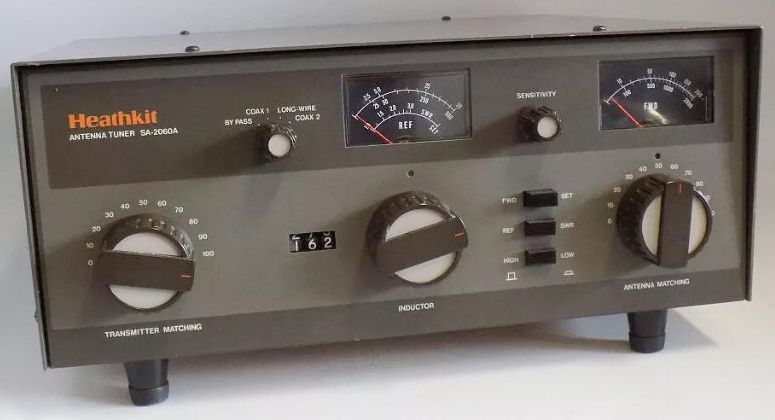
The SA-2060 and SA-2060A are the same basic tuners as the SA-2040 (there was no SA-2050), to which a number of additional features have been added. The most obvious of these additional features is the dual wattmeter and SWR bridge. The wattmeter reads 0-200 and 0-2000 watts forward and 0-50 and 0-500 watts reflected with 5 percent accuracy. The wattmeter/SWR sensor is factory assembled and calibrated.
Other added features include an extension of the tuning range down to 1.8 MHz.
Front panel controls include transmitter match, inductor, antenna matching, SWR sensitivity, and a switch to select one of two coaxial lines or a bypass (to a dummy load or resonant antenna, for example). Three front panel pushbuttons control the operation of the wattmeter.
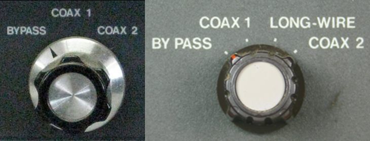
The major difference between the SA-2060 and the 2060A is the way the antennas are selected. When you use the SA-2060 with a random wire or balanced line you must have an open output at one of the two coaxial line connectors, otherwise you will have two antennas connected at once.
This precaution is not necessary with the 2060A—Heath added a position to the front panel antenna selector switch to enable the selection of a long wire or balanced line as well as the coaxial lines. Refer to Figure 1. There are no additional connectors on the rear panel.
The styling was also changed in the A version. The black cabinet and light green front panel was changed to a two-tone brown to match the SS-9000 transceiver. SS-9000 style knobs also replaced the familiar SB style knobs of the 2060.
Rear panel connections include an SO-239 input connector and three SO-239 outputs (coax 1, 2, and bypass). There are also three standoffs for use with a balanced line or random wire (but not both simultaneously).
Refer to the Preset Chart shown in Figure 2 for values used to preset the tuner. These settings will help in establishing final working values.
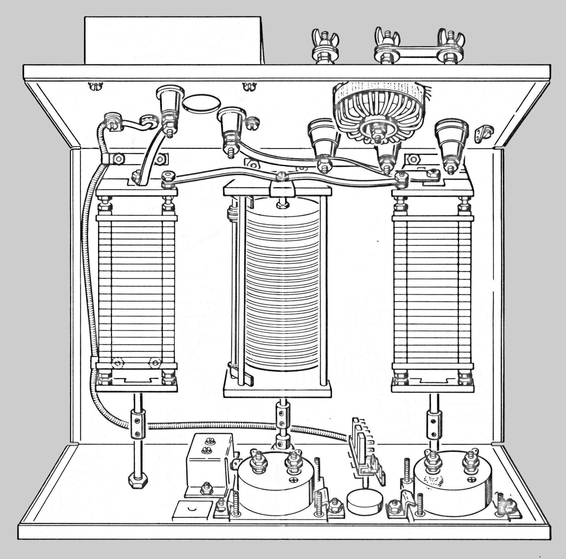
Note: When you turn the roller inductor, be careful that you do not turn it past its end stops. This could cause the roller contact to jump off the wire turns on the inductor.
Caution: The box on the rear panel containing the SO-239 connectors houses the power and SWR sensor circuits. This assembly was preassembled and adjusted. Adjustment of the sensors is not advised without the proper documentation.
These tuners are build on a copper plated chassis. They are rugged and well designed.
References:
Review. QST. Jul 1982, p. 40.
Frequency range: 1.8 to 30 MHz
Input power capability:
SSB: 2000 watts PEP
CW: 1000 watts
Input impedance: 50Ω
Output impedance: wide range
Meter functions: forward and reflected average power, and SWR
Meter ranges:
forward: 0-200 and 0-2000 watts
reflected: 0-50 and 0-500 watts
SWR: 1:1 to 3:1
Wattmeter accuracy:
forward: 200/2000 watts: ±5% (average)
reflected: 500 watts: ±5% (average)
reflected: 50 watts: ±7.5% (average)
Insertion SWR: 1.1:1
Photos, general information and specifications from "Heathkit: A Guide to the Amateur Radio Products," by Chuck Penson, WA7ZZE. Used with permission.