Note
In the introduction of the six-meter HW-29 assembly manual Heath said, “Extensive proof building and field testing over a period of several months have provided conclusive evidence that the HW-29 transceiver will provide highly reliable service…"
And yet.
Almost immediately upon the release of the HW-29 Sixer in 1960, it became clear that the unit had a couple of significant problems. The radio's regenerative receiver was radiating a respectable signal and getting into TV sets at a considerable distance. Additionally, the Sixer had been designed to use a 10 MHz crystal so that it would also oscillate at the fifth overtone. This scheme also proved problematic for crystal activity and stability. Heath quickly redesigned the rig to solve the receiver problem and changed the transmitter oscillator section to include a multiplier stage to allow for the use of 8 MHz crystals.
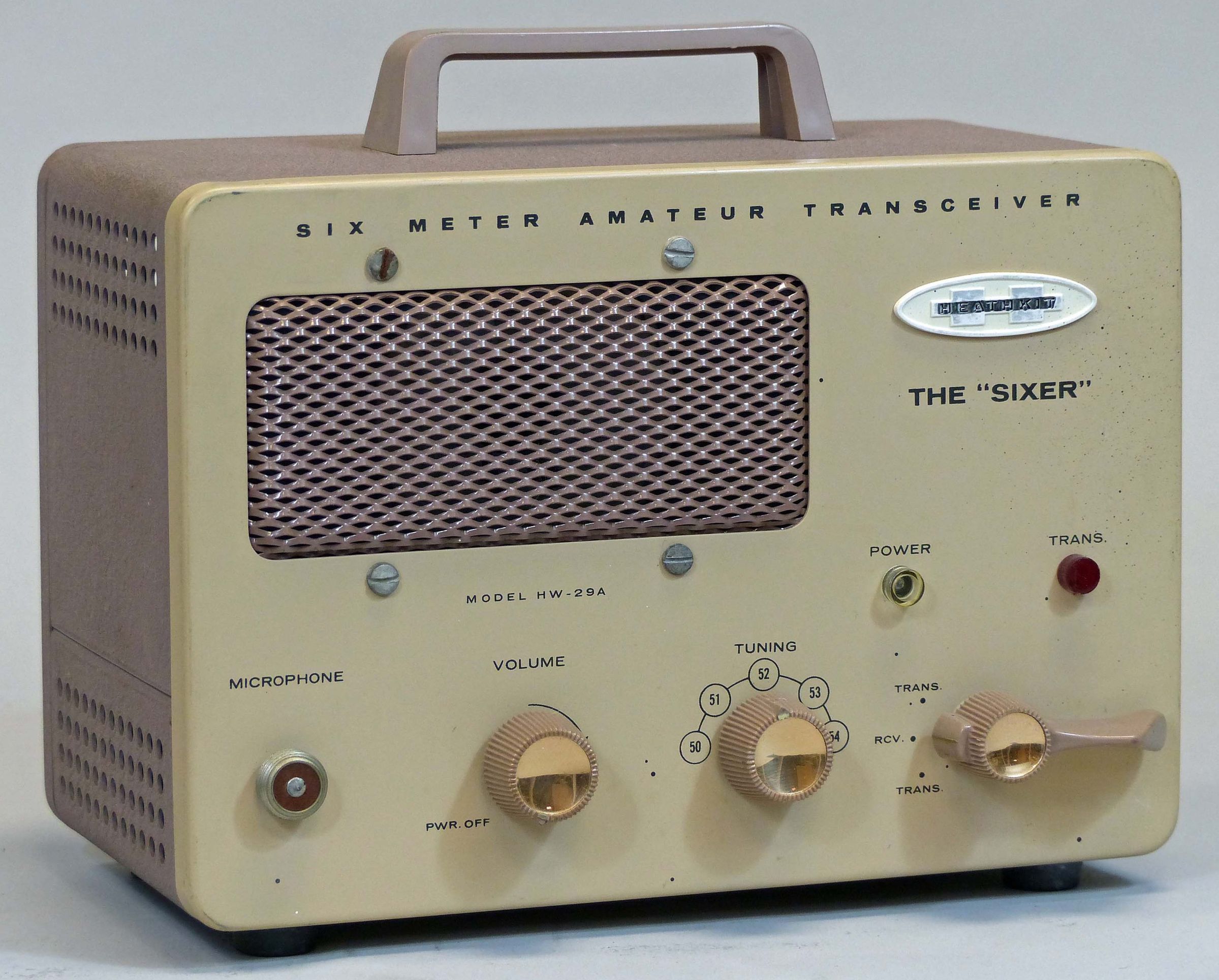
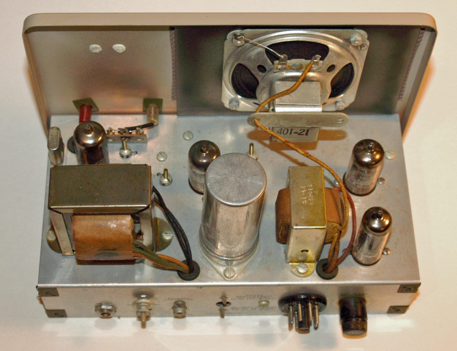
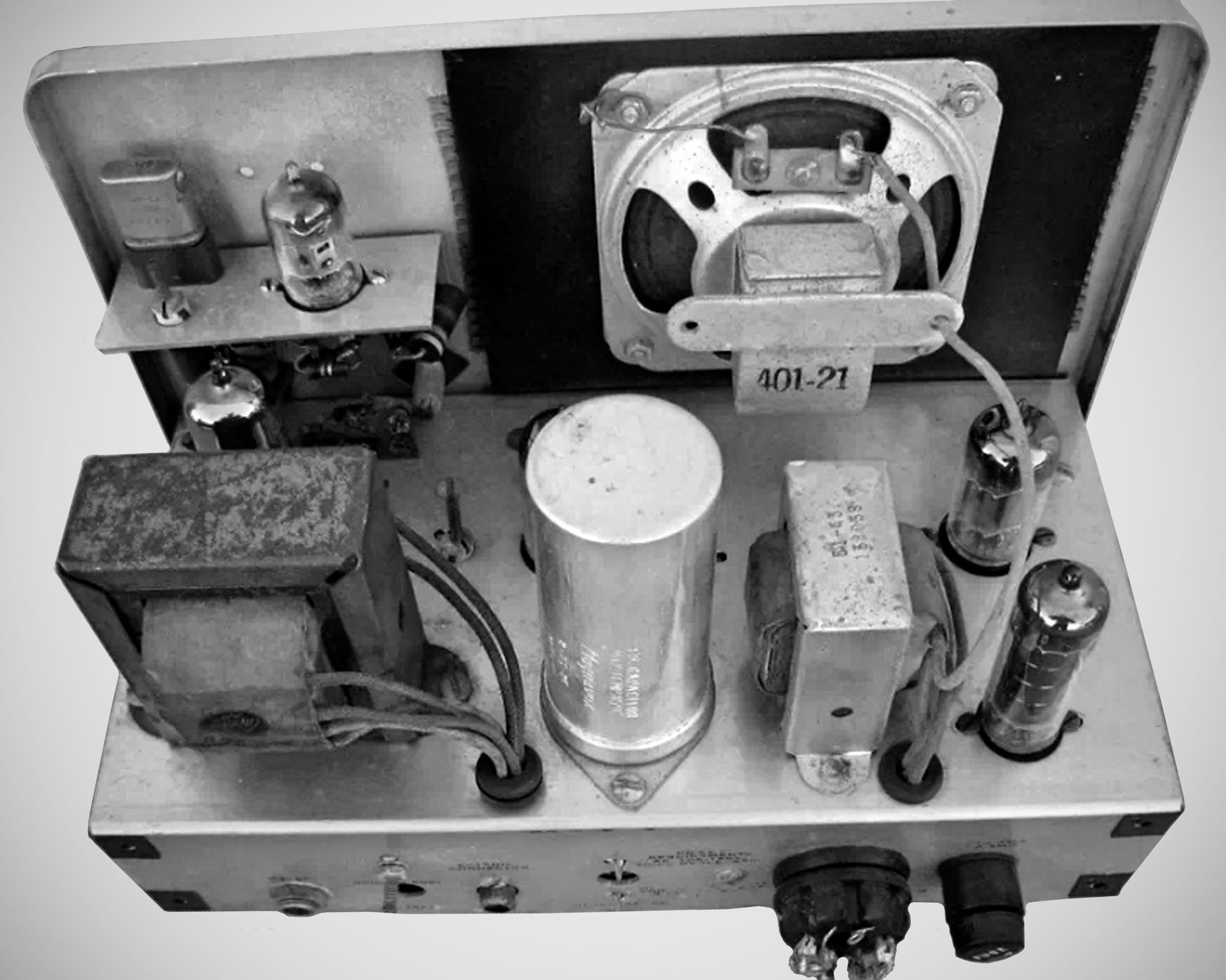
The new improved version was released as the HW-29A, and a modification kit was offered to owners of the original. The modification involved the installation of a small sub-chassis with a tube, a new crystal socket, and a coil. This assembly was attached to the inside of the front panel just below the Heathkit nameplate and required drilling two holes in the front panel. See photo.
It is likely that only a few hundred of the original HW-29 units ever got out the door.
CRYSTAL FREQUENCY CALCULATION
HW-29: Operating frequency = crystal frequency x 5
HW-29A: Operating frequency = crystal frequency x 6
Refer to HW-19 for additional discussion.
References:
Review. CQ. Nov 1960, p. 153.
Several notes on modifications. QST. Oct 1960, p. 50.
Modifications. Popular Electronics, Nov 1960, p. 86.
Add an S Meter. 73 Amateur Radio. Jul 1961, p.28.
AC/DC supply, new oscillator for a VFO. 73 Amateur Radio. May 1962, P. 16.
50% power increase. 73 Amateur Radio. Dec 1962, p. 9
Motor tuning to scan the band. QST. Apr 1963, p. 48.
Double sideband for. CQ. Apr 1963, p. 67.
Modification. CQ. Oct 1963, p. 34.
A linear amplifier for. 73 Amateur Radio. Sep 1964, p. 11.
Simple improvements. 73 Amateur Radio. Dec 1964, pp. 26, 28.
Easier final tuning. QST. Aug 1965, p. 71.
Add a final tuning control. QST. Jan 1967, p. 50.
Some useful modifications. QST. May 1968, p. 28.
Restoring. Electric Radio. Nov 1998
Spotting switch. Ham Radio. Dec 1969, p. 84.
TVI fix. 73 Amateur Radio. Mar 1970, p. 60.
Improved fusing. 73 Amateur Radio. Jan 71, p. 45
Review. Electric Radio. Mar 2007
Frequency coverage: 50 to 54 MHz
Crystal frequency range:
HW-29: 10000 to 10800 kHz
HW-29A: 8333 to 9000 kHz
RF input power: Approximately 5 watts
RF output power: 3.5 to 5 watts
Crystal type:
HW-29: HC-6/U
HW-29A: FT-241 or FT-243
Modulation: AM plate modulation, limited to less than 100%
Output impedance: 50 to 72Ω
Receiver type: superregenerative detector preceded by RF amp
Sensitivity: Usable with signals as low as 1.0 µV
Selectivity: not specified
Audio output power: 1 watt
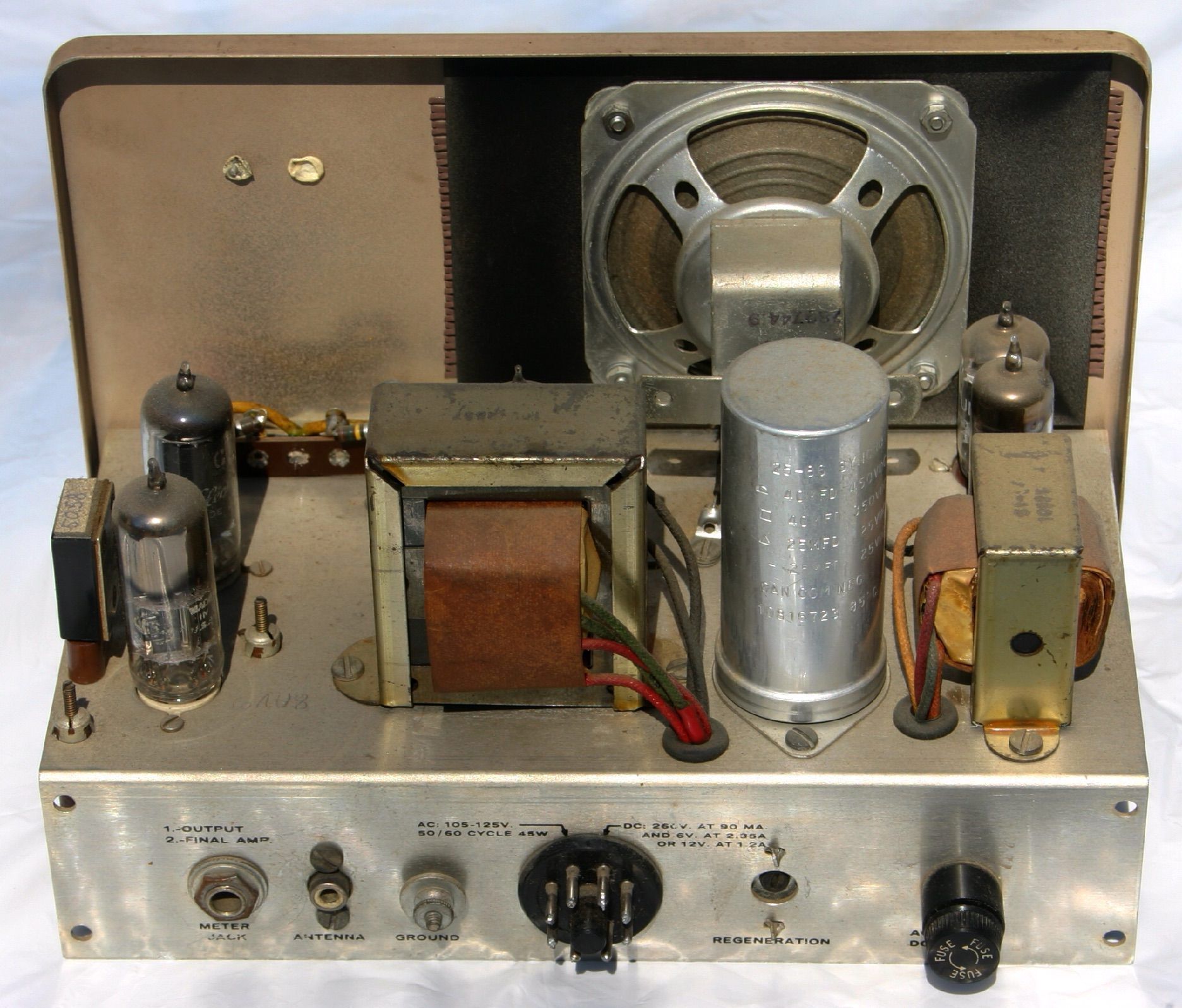
Power requirements:
HW-29: 120 VAC, 50/60 Hz, 35 watts
HW-29A: 120 VAC, 50/60 Hz, 45 watts
or external power supply like the VP-1-6 or VP-1-12; or a modern power inverter for battery operation
Size: 8 high x 9.75 wide x 6 deep (including knobs and handle); Weight: 6.5 lbs
Tubes: HW-29: (1) 6AU8, (1) 6AN8, (1) 12AX7, (1) 6AQ5
Tubes: HW-29A: (1) 12AX7, (1) 6AQ5, (1) 6CL6, (1) 6AN8, (1) 6BA8A
Photos, general information and specifications from "Heathkit: A Guide to the Amateur Radio Products," by Chuck Penson, WA7ZZE. Used with permission.