Note
QST, Mar 1954, p. 134.
90801 operating manual
Millen catalog 1959
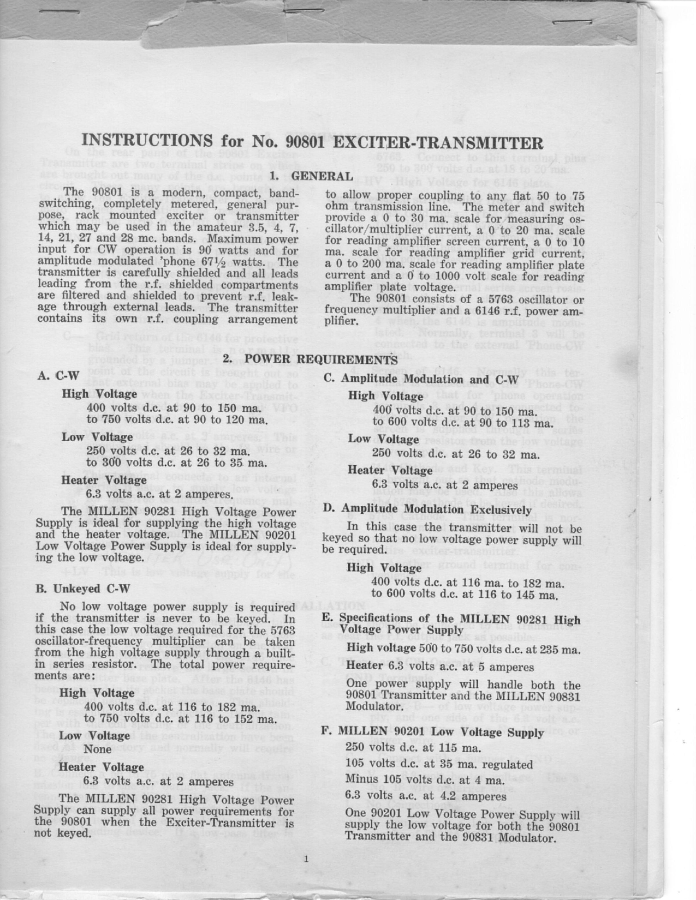
An improved version of the 90800 with band switching, so that no coil swapping is required. Based on a transmitter design in the December 1952 issue of QST, page 23. The original Millen schematic indicate a design date of July 1953. It did not appear in QST until March 1954.
Uses a 5763 as an oscillator/multiplier circuit feeding a 6146 final amplifier. The label on the front panel calls the 90801 a 50 watt transmitter. This probably refers to actual power out. Maximum input power is 90 watts CW, and more than 65 watts on AM. In addition to the change to band switching, the 90801 has also been TVI proofed through extensive RF shielding. Requires an external power supply.
The meter reads to 30 mA for the oscillator/multiplier, 20 mA for the amplifier screen, 10 mA for the amplifier grid, 200 mA for amplifier plate current, and 1000 volts for the amplifier plate.
A companion modulator (90831) was also produced for the 90801 transmitter. The modulator is built in a similar sized rack cabinet.
The transmitter has its own coupling circuit and will permit matching to any 50 or 75Ω line.
Power requirements:
High voltage: 400–750 VDC @ approximately 150 mA
Low voltage: 250–300 VDC @ approximately 35 mA
Filament: 6.3 volts @ 2 amps
Power input:
90 watt maximum for CW
67.5 watts maximum for AM
The voltages can be provided by the Millen 90281 high voltage power supply, and the 90201 low voltage supply. These units can power both the exciter and modulator.
Frequency coverage: 80–10 meters
Tubes: (1) 5763, (1) 6146