Note
The SB-614 is the solid state replacement for the HO-10 and SB-610, though it still uses a cathode ray tube. It serves the same basic purpose—to monitor transmitted RF energy—and is styled to match the SB-104 transceiver.
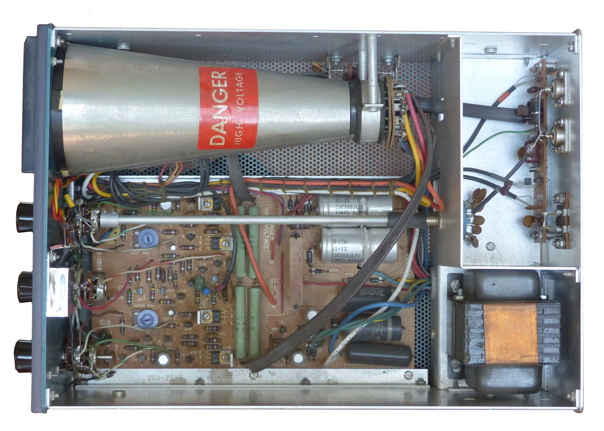
The SB-614 is built on two PC boards and uses 26 transistors and a handful of diodes. No ICs are used.
There are a few significant differences between the SB-614 and the SB-610.
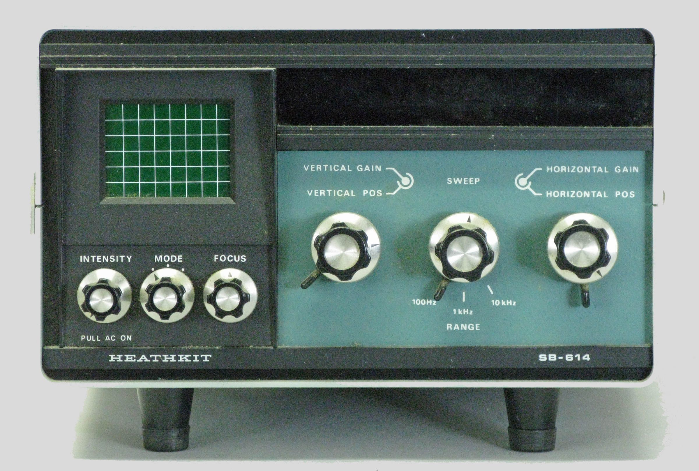
First, the visible area of the CRT has been masked into a small rectangle, and the grid changed from 8x8 to 8x6. This reduces the visible vertical dimension by 25%.
Second, with the SB-614 Heath gave up the idea of being able to monitor incoming signals. The HO-10 and SB-610 could be tapped into the receiver IF to provide a look at the other fellow’s signal. This idea is intrinsically flawed, however, as there are too many things that can effect the waveforms you see displayed, including QRM, atmospheric noise, AGC and any problems or shortcomings your receiver might have. In the SB-614 manual Heath still suggests this can be done, but the connection used to do it is to the station speaker. Thus the display seen on the scope may be interesting to look at but is useless for all practical purposes.
Third, the two-tone generator has been eliminated, making it impossible to determine the linearity of your SSB signal unless you provide your own tones externally. The 614 can, however, be useful for RTTY work and as a simple oscilloscope. As an oscilloscope the 614’s vertical frequency response is from 10 Hz to about 50 kHz, with reasonable sync capability.
Fourth, to monitor transmitted RF energy the 614 requires a minimum of 10 watts of drive. Since there is no low power option as in the SB-610, the SB-614 cannot be used with CB or QRP equipment.
The 614 is advertised as covering only 80 to six-meters—no 160 meter coverage as with the HO-10 and SB-610. Caution: Use of the SB-614 on six-meters may present a high SWR (as high as 6:1) to your transmitter.
Caution: When changing transmitter power levels care must be taken to keep the vertical height of the display within the bounds of the graticule (the markings on the screen). Failure to do so may result in the overheating and/or destruction of a resistor (R201) and a coil (L201). To complicate matters, the potential for damage to these components exists even when the 614 is turned off. It would be prudent, therefore, to keep the vertical gain control in its full counter-clockwise position unless the scope is on and the trace can be seen.
Front panel controls include power on/off/intensity, mode, focus, vertical position and gain, horizontal position and gain, and sweep speed (and vernier adjust). Indicator lights behind the red window indicate SSB, TRAP, or CROSS (RTTY) mode.
Internal controls include vertical and horizontal balance. These are used to adjust the linearity of the trace and are accessible by removing a rear panel access plate.
Rear panel controls include astigmatism and a two-position attenuator. Rear panel connections include a pair of loop-through SO-239s for RF input and output, a pair of loop-through RCA jacks (exciter input for linearity checks), and RCA jacks for vertical and horizontal input for RTTY or oscilloscope use. The missing features, combined with the price tag and problems with the SB-104, (for which the 614 was designed), held sales down, and the 614 never achieved the popularity of its predecessors. Still, Heath sold the 614 for nine years, and units show up at swap meets with some regularity. The 614 is finished in the standard two-tone green wrinkle paint.
Warning: Lethal voltages present when operating. Caution: Handle cathode ray tubes with great care.
References:
Review. QST. Jun 1976, p. 37.
Review. CQ. Aug 1976, p. 40.
Extend the versatility. QST. Jan 1982, p. 36.
RF SAMPLING SECTION
Frequency coverage: 3.5 to 54 MHz
Sensitivity: 0.25 inch defection at 10 watts, 0.74 inch deflection at 100 watts
RF power limits:
exciter input: 10 to 300 watts
antenna input: 10 to 1000 watts
Loss insertion: negligible
VERTICAL AMPLIFIER
Input impedance: 1MΩ shunted by 75 pF
Sensitivity: 60 mV per 0.25 inch deflection
Attenuator:
X1: 1 volt rms maximum
X10: 10 volts rms maximum
Frequency response: 10 Hz to 50 kHz typical
HORIZONTAL AMPLIFIER
Input impedance: 1MΩ
Sensitivity: 60 mV per 0.25 inch deflection
Frequency response: 10 Hz to 3 MHz typical
SWEEP GENERATOR
Type: recurrent, auto sync
Frequency range: 10 Hz to 10 kHz in 3 ranges
GENERAL
Power requirements: 120/240 VAC, 50/60 Hz, 35 watts
Tube: 3RP1A CRT
Photos, general information and specifications from "Heathkit: A Guide to the Amateur Radio Products," by Chuck Penson, WA7ZZE. Used with permission.