Note
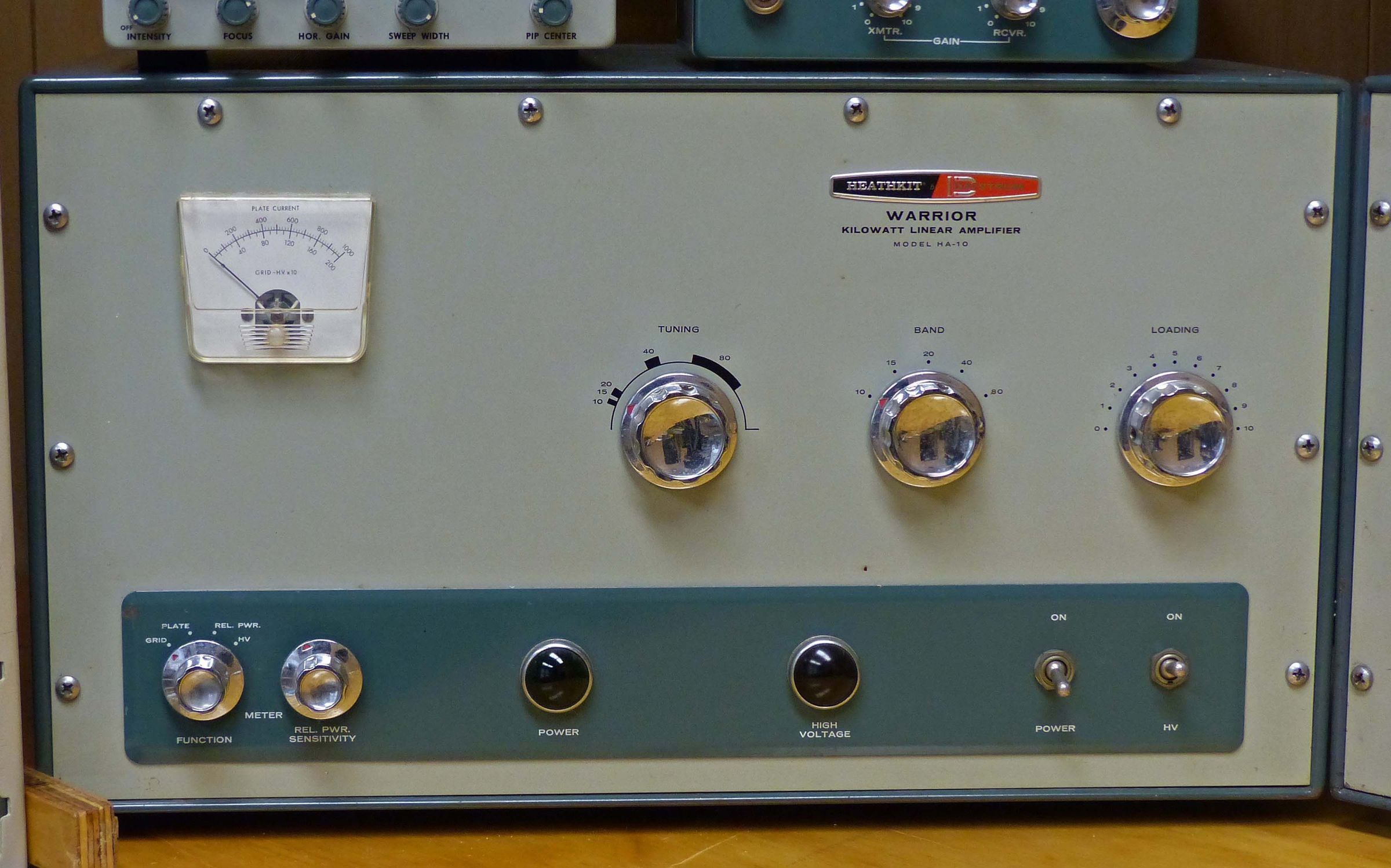
The HA-10 was Heath’s first real success in a linear amplifier and the first Heath product ever to be offered as a kit or factory assembled. It was designed to complement the TX-1 or HX-10, and to replace the too big, too heavy, and much too expensive KL-1 “Chippewa,” and its equally big, heavy, and expensive power supply, the KS-1. In the HA-10, Heath combined the amp and its power supply into a single cabinet the size of the Chippewa amplifier section alone—and sold it for about half the price of the KL-1/KS-1 combination.
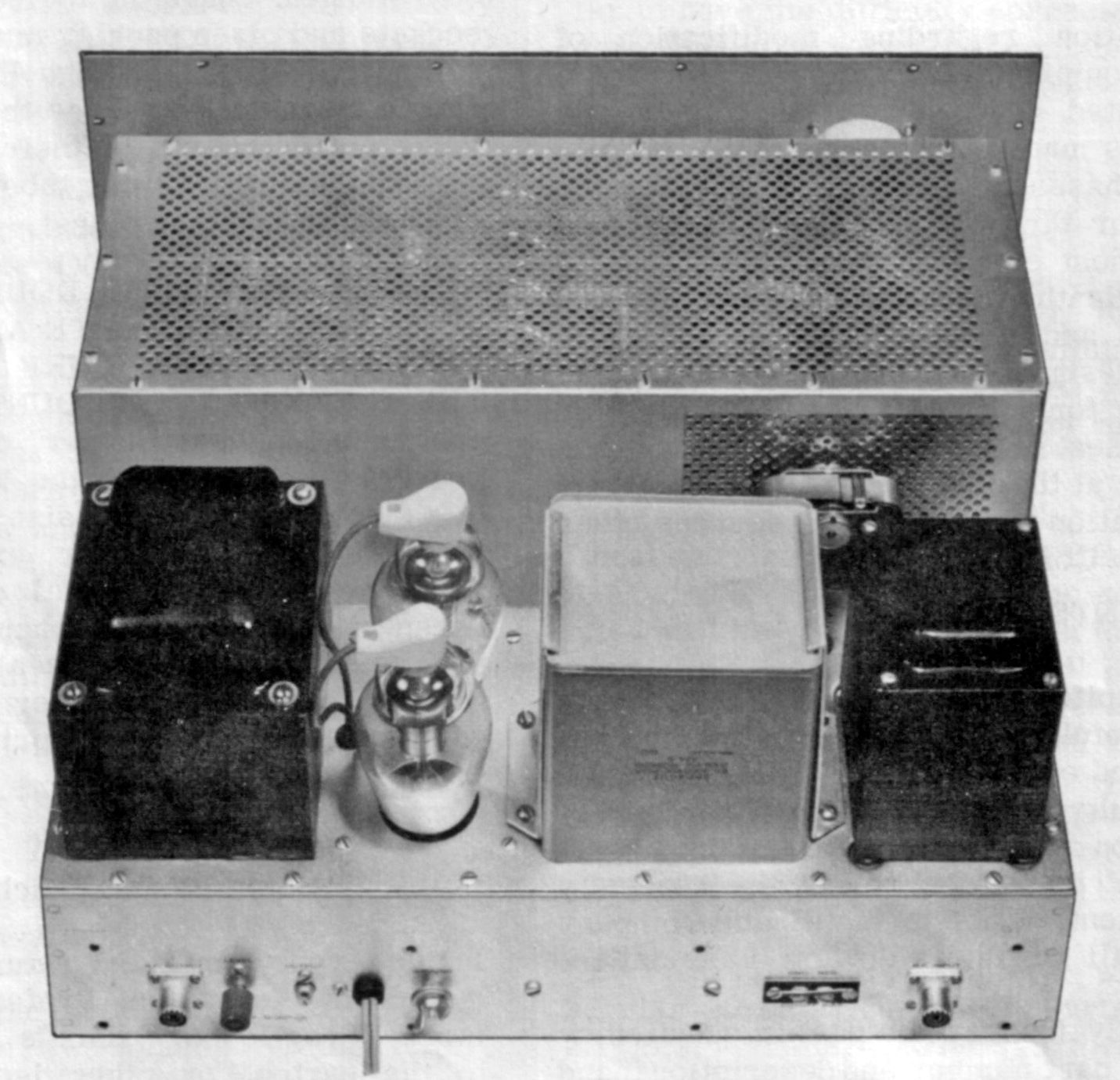
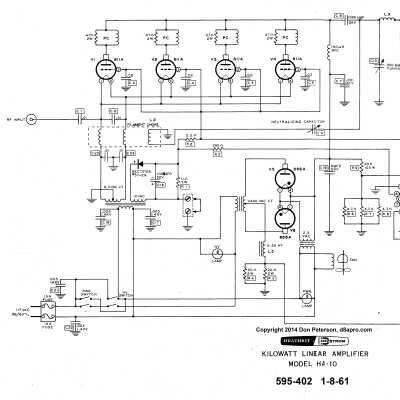
The HA-10 uses two 866As in its power supply (which runs around 1300 volts key down and fully loaded) and four paralleled, fan-cooled, 811As running class B. Together, they develop around 1000 watts PEP/CW and about 400 watts AM—a respectable signal by any definition—requiring only 50-75 watts of drive. The HA-10 covers 80 through 10 (but not 11) meters and operates AM, SSB, and CW.
The amplifier is built on a 16-gauge steel chassis with an 1/8-inch thick aluminum front panel. It is enclosed in a one-piece welded copper-clad TX-1 style cabinet painted in the now familiar two-tone green colors.
The HA-10’s broadband input circuit requires no tuning and will match about 70Ω.
The output circuit is a variable Pi-network with an impedance of 50 to 75Ω to an SO-239 RF connector. There is also a monitor scope output with a level control. The front panel meter reads grid, plate, relative power, and high voltage. A bias supply ripple problem was solved in the first few weeks of production.
Beware the fused power plug.
Caution: 866A tubes contain mercury
Warning: Lethal voltages present while operating.
References:
Review. QST. Jun 1961, p. 44.
Review. 73 Amateur Radio. May 1962, p. 68.
Review. 73 Amateur Radio. Dec 1962, p. 60.
Improved bias circuit. QST. Dec 1961, p. 62.
Improved bias circuit (more on). QST. Feb 1962, p. 33.
Improved bias circuit. CQ. Feb 1962, p. 84.
Better bias filter. CQ. Oct 1961, p. 100. ERROR
Rectifier noise. CQ. Nov 1961, p. 99.
Use with TX-1/SB-10/phone patch. CQ. Jul 1962, p. 80.
Impulse interference fix. CQ. Sep 62, p. 67.
Increasing plate voltage. 73 Amateur Radio. Feb 1964, p. 12.
Use on 6 meters. CQ. Feb 1966, p. 76.
Improved performance. Ham Radio. Oct 1971, p 68.
Drive power: 50 to 75 watts (depending on frequency)
Maximum input power:
SSB: 1000 watts PEP
CW: 1000 watts
AM: 400 watts (500 watts using controlled carrier modulation)
RTTY: 650 watts (load to only 430 mA plate current)
Output impedance: 50–75Ω
Input impedance: about 70Ω (broadband, no tuning required)
Power supply: filament, bias, 1500 VDC plate, and blower power
Power requirements: 120 VAC, 50/60 Hz, 1250 watts maximum
Tubes: (4) 811A, (2) 866A.
Photos, general information and specifications from "Heathkit: A Guide to the Amateur Radio Products," by Chuck Penson, WA7ZZE. Used with permission.