Note
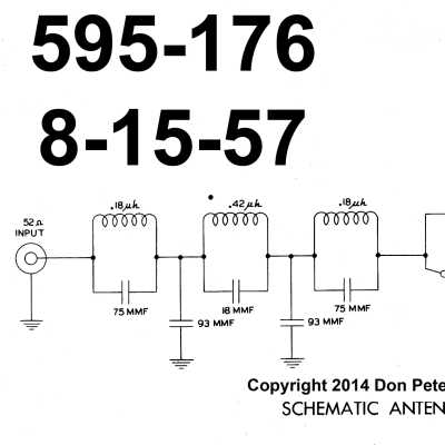
The AC-1 is a simple transmatch and was released as a companion product for the AT-1 transmitter. It is designed to work with random wire antennas (at least 75 feet long) from 80 through 10 meters and contains an L-section-tuning network.
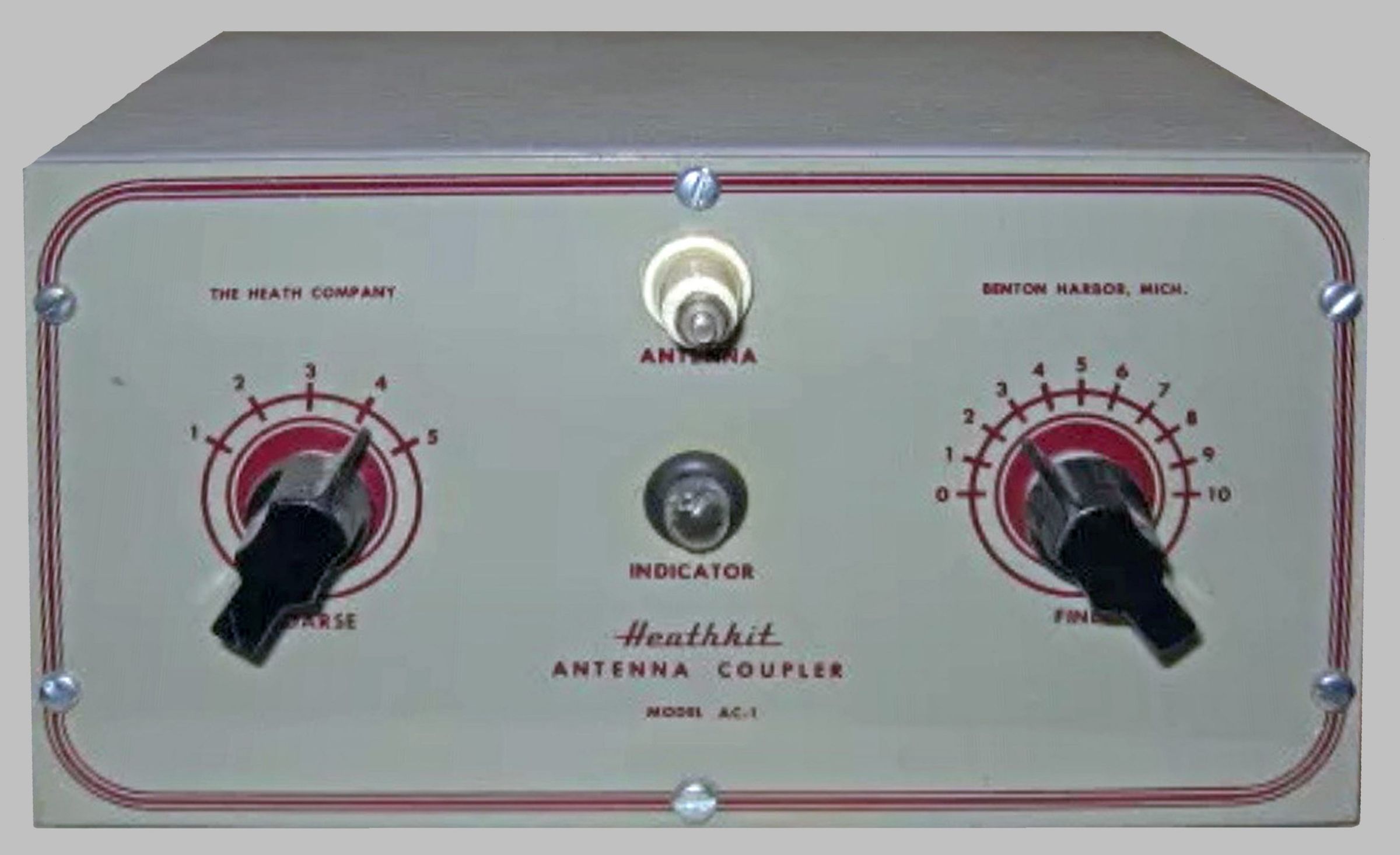
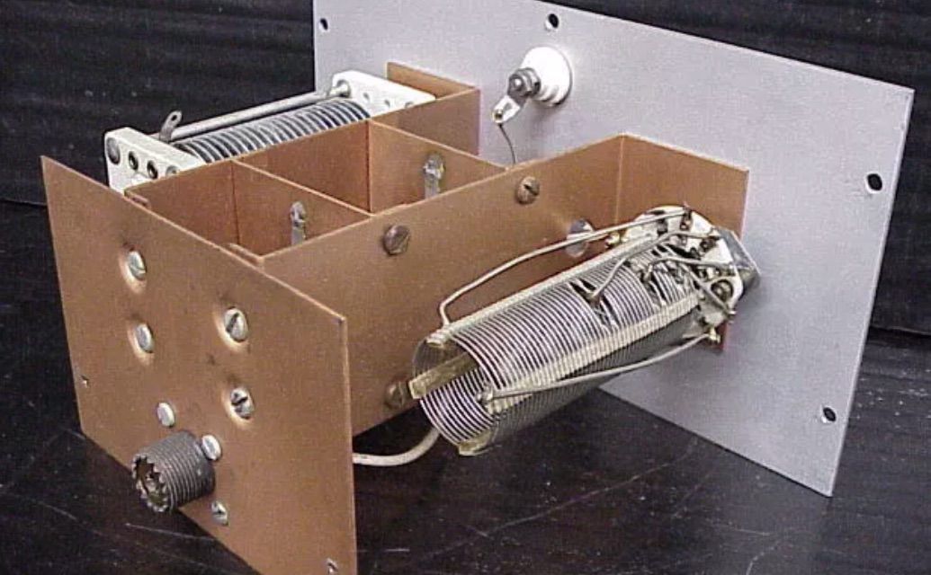
The unit features a tapped inductor for coarse adjustment, a variable capacitor for fine adjustment, a neon lamp tuning indicator, and a 36 MHz low-pass filter. The AC-1 will handle 75 watts, has a rear panel SO-239 input connector, and a front panel porcelain stand-off binding post for the output.
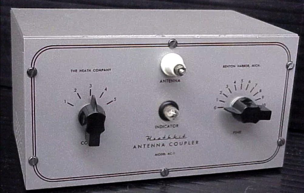
Three versions of the AC-1 have been noted. The early version used the same paint scheme as the pre-classic test equipment products (a kind of beige with maroon dial markings and triple pinstripes), black double indent knobs and dial markings including complete circles. A variation of this design changed the dial markings. The last version reduced the pinstripes from three to two and deleted the pre-classic paint scheme in favor of a plain aluminum finish similar to the AT-1. This version is also found using the same gray knobs as the AM-2.
References:
Review. Electric Radio. Apr 2016.
Series or parallel tuning with. QST. Dec 1958, p. 71.
Maximum RF power input: 75 watts
Input connection: 50 Ω, SO-239
Output connection: single-ended ceramic standoff
Low-pass filter cut-off: 36 MHz
Photos, general information and specifications from "Heathkit: A Guide to the Amateur Radio Products," by Chuck Penson, WA7ZZE. Used with permission.