Note
Lafayette catalog number 88 (1947), p. 99.
QST, Dec 1948. p. 138.
QST, Jun 1951. p. 126.
Walter Ashe catalog, 1954, p. 9.
Two versions of the 90711 were produced. The original, which first appeared in the 1946 catalog, was replaced with the more refined version (with the same model number) in 1947. The first ad in QST was for the later version: QST, Dec 1948. p. 138.
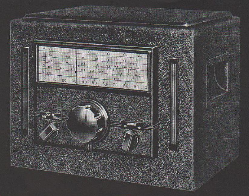
EARLY VERSION
Uses a stable gang-tuned electron coupled oscillator and amplifier, with a regulated power supply, and features high or low impedance output with enough power to "drive any tube up to an 807."
The output is on 80 or 40 meters with an accurately calibrated full-vision band spread for each band, and dial calibrations for 10, 15, 20, 40, and 80 meters. There are provisions for complete control of the transmitter.
Stability is provided by a high capacitance oscillator grid circuit, an untuned oscillator plate circuit, a large temperature compensated grid coil, temperature compensated capacitors, regulated plate and screen voltages for the oscillator, adequate ventilation and carefully designed layout.
Uses the Millen 10035 panel dial with a drive ratio of 13:1.
Band change is accomplished with a front panel switch. There are no pug-in coils.
The output may be coupled to a low impedance coupling link; or, by means of to high impedance through the adapter on the end of the output cable. This can be connected to the crystal socket, or directly to the grid.
The 80 meter output may be used on 80 and 40 meters, and the 40 meter output can be used on 20, 15 and 10 meters.
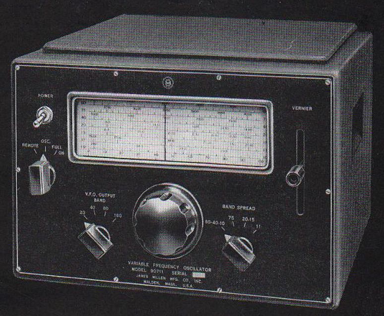
LATER VERSION
The same basic functionality as the original, but with a few of added features and a new tube lineup.
This version adds a vernier tuning lever on the right side of the tuning window, and a switch--separate from the tuning range switch--for the output band. This permits any tuning range to be used with any output band.
Also added were a separate calibrated band for 75 meters, and a function switch which can be used to turn on the oscillator alone, the entire VFO, or can select remote control, so that the VFO can be controlled by the station master transmit-receive switch.
Tuning range:
80 meters – 3490 to 3730 kHz
75 meters – 3720 to 4010 kHz
40 meters – 6980 to 7440 kHz
20 meters – 13975 to 14425 kHz
15 meters – 21000 to 21600 kHz
11 meters – 26960 to 27430 kHz
10 meters – 28000 to 30000 kHz
Power (both versions): 105–125 VAC, 50-60 Hz, 60 watts
Tubes (original version): (1) 6SK7, (1) 6L6, (1) 5Y3, (1) VR-150, (1) VR-75
Tubes (later version): (2) 6SK7, (1) 6AG7, (1) 5Y3, (1) VR-150