Note
QST, Nov 1939, p. 73.
Radio Craft, Dec 1939, p. 365.
Lafayette catalog number 87 (New York), p. 58.
QST, Aug 1944, p. 75.
QST, May 1945, p. 63.
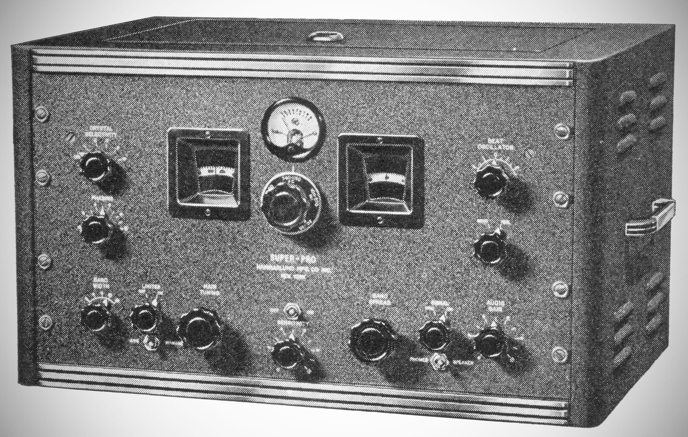
The Hammarlund SP-200 series, which was introduced in 1939, was an 18 tube single conversion receiver. It was a significant evolution of the Super-Pro line and saw widespread use during World War II. The variations within the series primarily centered on frequency coverage and military-specific modifications.
The Hammarlund SP-100 and SP-200 were both "Super-Pro" receivers, building upon the original SP-10. However, the SP-200, introduced in 1939, represented a significant maturation of the design, making it a more robust and complete professional instrument, especially in anticipation of World War II.
Here are the key differences between the SP-200 and the earlier SP-100:
Tube Technology: The SP-200 saw a complete standardization to all-metal tubes (e.g., 6K7s, 6L7, 6J5s, 6F6s) across all stages. This provided superior shielding, reduced microphonics, and enhanced durability, which was crucial for military and heavy-duty commercial use.
Crystal Filter: With the SP-200, the crystal filter became a standard feature. This reflected its increasing importance for high-precision communications, especially for CW reception, where extremely sharp selectivity was required to cut through interference. The phasing control for the crystal filter was also standard.
Tube Count: The SP-100 had 14 tubes on the main chassis plus 2 in the power supply (total 16). The SP-200 increased to 16 tubes on the main chassis plus 2 in the power supply (a total of 18 tubes). This increase reflected additional amplification stages and tubes for improved performance or features like the S-meter amplifier.
Audio Output Stage: The SP-200 standardized on a push-pull 6F6 audio output stage, driven by a 6J5. This delivered a powerful 14 watts of clean audio, making it excellent for monitoring and even for high-fidelity broadcast listening.
Bandwidth Control Scale: On the SP-100, the selectivity control was often simply labeled "Selectivity." With the SP-200 the control was typically labeled "Band Width" and was engraved with calibrated bandwidth values (3-16 kHz), offering more precise control and indication to the operator.
Military Proliferation:
The SP-100 saw some limited military use, with specialized variants like the SP-110-LX for low-frequency applications.
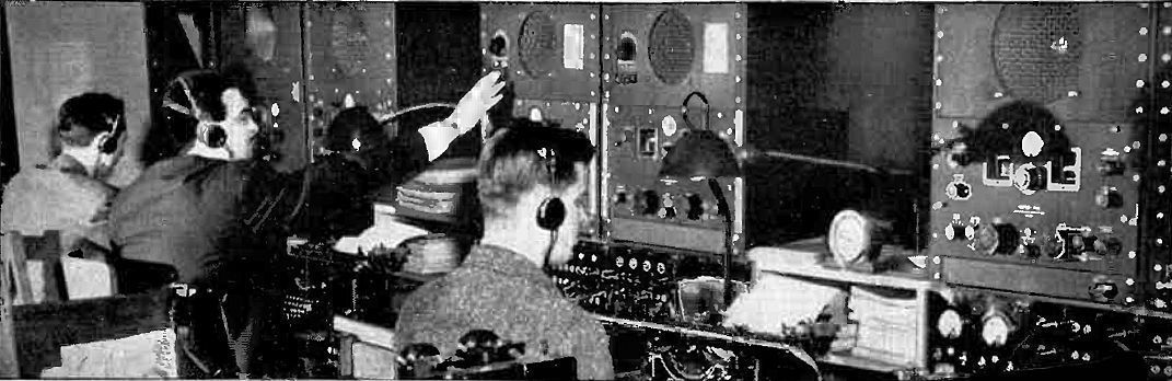
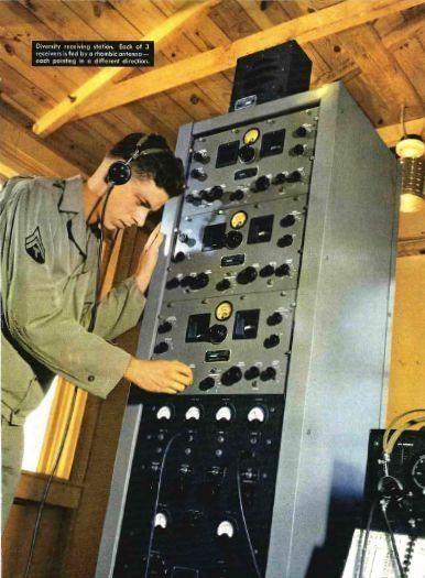
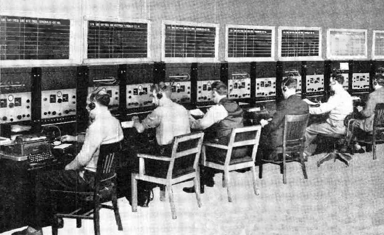
The SP-200 became the dominant and primary communications receiver for the U.S. military during World War II, receiving widespread production and numerous official designations like BC-779, BC-794, and BC-1004. Its design was inherently more suited to the rigors and continuous operation demanded by wartime.
Physical Details & Construction Refinements: The SP-200 often had minor but important mechanical refinements over the SP-100, such as changes in the S-meter housing (full glass front replaced with partial glass and zero adjust mounted in metal), and changes to terminal blocks (e.g., for the relay pin jack, moving from a fiber block to a screw terminal block). These were often about enhancing ruggedness and serviceability.
In essence, the SP-200 built on the successful foundation of the SP-100 by fully embracing metal tube technology, making the crystal filter a standard feature, and generally refining the design for maximum ruggedness and performance in critical professional and military applications. It represented the peak of Hammarlund's pre-war Super-Pro development.
The basic models are these:
SP-200-X (540 kHz to 20.0 MHz)
SP-200-SX (1.2 to 40 MHz)
SP-200-LX (100 to 400KC kHz, and 2.5 to 20.0 MHz)*
*Note that some published sources, including Riders, specified that the LX version covered 150 to 300 kHz. This is almost certainly an error.
As in the SP-100 series, the SP-210 and SP-220 nomenclature referred to the size of the speaker supplied–10 inch and 12 inch respectively. Rack mount version were also available.
Military Designations: The SP-200 series was a cornerstone of military communications during World War II, and as such, it was given a number of official military designations. Some of the most common military designations were:
BC-779: This was one of the most common military versions. It was a general-purpose receiver with a frequency range similar to the SP-200-X, covering 0.1 to 0.4 MHz and 2.5 to 20 MHz.
BC-794: This variant had a higher frequency range, often covering 1.25 to 40 MHz, making it a counterpart to the commercial SP-200-SX.
BC-1004: Another military designation, the BC-1004 covered a range from 0.54 to 20 MHz.
R-129/U and R-270/FRR: These were later military model numbers that also referred to variations of the SP-200 design.
The differences between these models were generally not in the core circuit design, but in the specifics of their frequency bands and the inclusion of features like crystal filters.
The SP-200 series, including the military versions, were designed with a separate power supply unit. This external power supply was a significant component, adding substantial weight to the overall system. Specifically, the SP-200 series used a separate power supply that contained tubes, including a 5Z3 B+ rectifier and an 1-V rectifier for the bias supply. The military versions of the SP-200, such as the BC-779, BC-794, BC-1004, and R-129/U, were documented in the Signal Corps manual TM-11-866, along with their corresponding power supplies RA-74, RA-84, and RA-94. The separate power supply for the SP-200 added 57 to 61 pounds to the overall weight of the receiver, which already weighed 73 pounds.
Main Chassis
(2) 6K7 (RF amp)
6L7 (mixer)
6J7 (local oscillator)
6K7 (first IF)
(2) 6SK7 (IF)
6H6 (detector)
6N7 (noise limited)
6SK7 (AVC amp)
6H6 (AVC rectifier)
6SJ7 (BFO)
6C5 (first audio)
(3) 6F6 (first audio and push-pull)
Power Supply
5Z3 (B+ rectifier)
80 (bias rectifier)
References
Brief description. Radio Craft, Nov 1939, p. 298.
Review. Radio News, Nov 1939, p. 29.
Review. Radio Craft, Dec 1939, p. 340.