Note
QST, Oct 1959, p. 3.
QST, Jun 1963, p. 161. (KWM-2A)
QST, Jul 1963, p. 2.
QST, Sep 1963, p. 2. (KWM-2)
QST, Seo 1973, p. 2. (KWM-2)
QST, Sep 1975, p. 2. (KWM-2A)
QST, Nov 1975, p. 2.
QST, Dec 1975, p. 2.
QST, Jan 1976, p. 2. (KWM-2A / 27,000 sold)
QST, Mar 1976, p. 2. (KWM-2A / 27,000 sold)
QST, Apr 1976, p. 2.
QST, May 1976, p. 2. (KWM-2A / 27,000 sold)
QST, Jul 1976, p. 2.
QST, Feb 1976, p. 117.
After the introduction of the KWM-2A, it and the KWM-2 were sold concurrently.
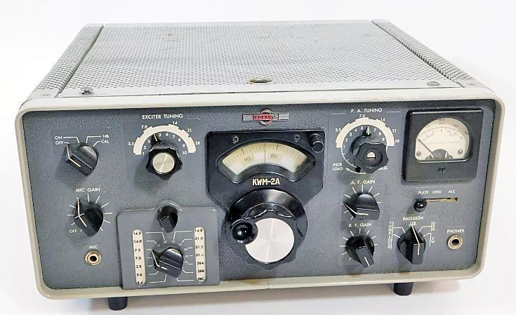
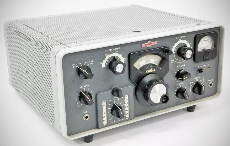
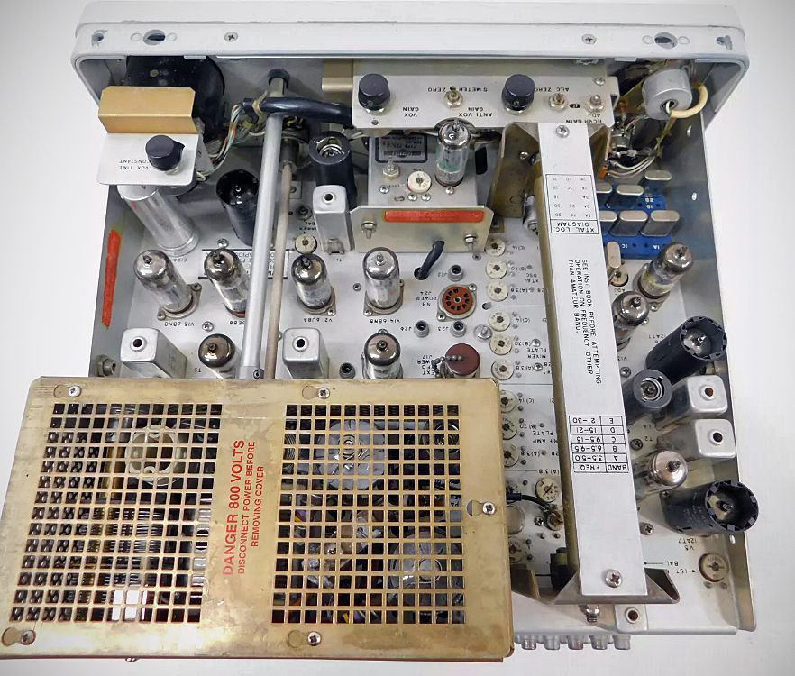
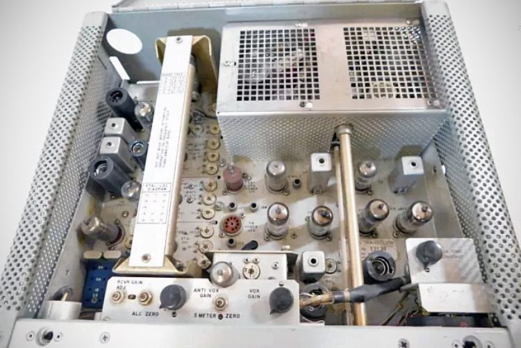
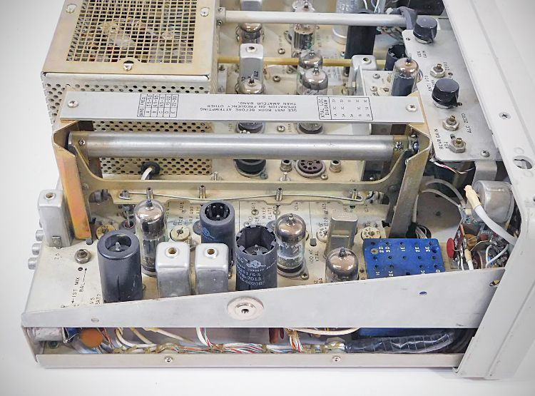
The KWM-2 transceiver combined the circuits of the 75S-1 and 32S-1 in a single package with frequency controlled by one PTO. It was styled to match the S/Line and was intended mainly for sideband operation on 80–10 meters. It had a pair of 6146 tubes in the final and ran 175 watts PEP input on SSB. The KWM-2 and its KWM-2A variant underwent a series of updates and improvements, remaining in production until the early 1980s.
The KWM-2A, released in 1961, is an extended frequency version of the KWM-2 for MARS (Military Affiliate Radio Service) and military applications. The KWM-2A has an additional crystal board permitting the operator to add 14 crystals to cover frequencies outside the amateur bands. A front panel switch and indicator permits instant switching between the two crystal boards.
An ad in the January 1976 issue of QST states that "...in the last 15 years some 27,000 KWM-2A units have been sold."
Basic Features
- Filter-type SSB generation
- Selectable sideband operation
- Automatic load control (keeps the signal level adjusted to its rated PEP, resulting in an increase in average talk power)
- Inverse RF feedback to improve linearity and reduce distortion products.
- A permeability tuned oscillator ("PTO") for better linearity and stability
- Dial division of 1 kHz
- CW break-in (though not true QSK) and sidetone
Front Panel Controls
OFF-ON-NB-CAL
EXCITER TUNING
ZERO SET
PA TUNING
LOADING
MIC GAIN
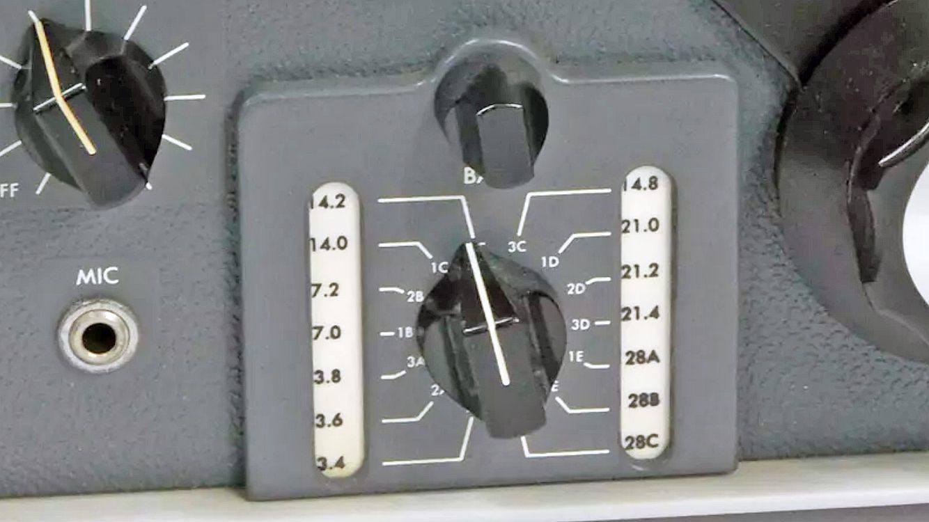
BAND SWITCH
AF GAIN
RF GAIN
EMISSION
METER SWITCH
SPECIFICATIONS
Frequency Range: 3.40–5.00 and 6.50–30.00 MHz
Crystals are provided for all HF bands except 10 meters where one crystal is supplied with provision for two additional crystals
Coverage (as provided, in MHz)
80 meters – 3.40–3.60, 3.60–3.80, and 3.80–4.00
40 meters – 7.00–7.20, and 7.20–7.40
20 meters – 14.00–14.20 and 14.20–14.40
WWV – 14.80–15.00
15 meters – 21.00–21.20, 21.20-21.40 and 21.40-21.60
10 meters – 28.50–28.70
Modes: USB, LBS, CW
Duty Cycle: SSB continuous; CW 50%
Calibration Accuracy: 1 kHz
Backlash: < 50 Hz
Visual Dial Accuracy: 200 Hz on all bands
Stability: Within 100 Hz after warm-up
Plate Input: 175 watts PEP SSB; 160 watts CW
Power Output: 100 watts PEP (nominal) into 50Ω
Output Impedance: Variable, 50 ohms nominal; will match 2:1 SWR
RF Feedback: Approximately 10 db of RF feedback around PA and driver for improved linearity
Harmonics and Spurs:
Carrier suppression -50 db
Unwanted sideband -50 db
Oscillator feed-through and/or mixer products -50 db
Second harmonic -40 db
Third order distortion -30 db
Noise Level: 40 db below single tone carrier
Sensitivity: 0.5 uv for 10 db signal-to-noise
Selectivity: 2.1 kc bandwidth at 6 db down; 4.2 kc bandwidth at 60 db down
Receiver Spurious Response: Image rejection better than 50 db. Internal
spurious below 1 µv equivalent antenna input
Audio Output: 1.0 watt maximum
Audio Input: High impedance microphone or phone patch
Frequency Response: 300-2400 Hz + 6 db
ALC: operates on IF and RF amplifier stages and is capable of 10 db compression
AGC: audio output level does not change more than 20 db as the input
signal is changed from 5 µv to 1 v. Fast attack and slow release provide excellent AVC action on voice and CW.
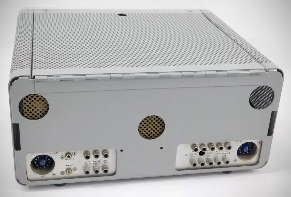
Power Requirements
800 VDC @ 175 ma
275 VDC @ 190 ma
Bias adjustable between –60 to –80 VDC
6, 12, or 24 VDC at 11.0, 5.5 or 2.75 amps respectively
115 VAC, 50-60 cps; 235 watts receive, 475 watts transmit
Size: (with feet) – 14-3/4″ W, 7-3/4″ H, 14″ D; Weight: 18 Lbs. 3 oz
References
RTTY with. CQ, Apr 1961, p. 34.
Independent receiver control. CQ, Mar 1963, p. 40.