Note
The VF-7401 was Heath’s last kit-type two-meter transceiver. It was well designed, and had plenty of power and features, but Heath was coming under intense pressure from competition. Sales were never as high as Heath had hoped for, and it is likely that Heath lost money on the 7401.
The VF-7401 was the last of the line that began with the HW-202. The transceiver was advertised as having a scanning feature, but that label is a little misleading. The 7401 has no “memory channels” as we have come to understand them. It scanned standard channel spacings.
Heath also advertised that it had “800 channel capacity.” Again this is misleading. What Heath meant was that there are 800 standard channel allocations between 144 and 148 MHz. The radio will scan these in 10 kHz step. 5 kHz divisions are possible only when scanning is stopped, and are achieved by a front panel pushbutton.
There are two basic scanning modes. In one mode the rig will scan until it comes upon a signal, at which point it will stop until told to continue. In the other mode it will stop and then resume scanning at the end of the transmission. In both cases the unit will only scan 1 MHz portions of the band.
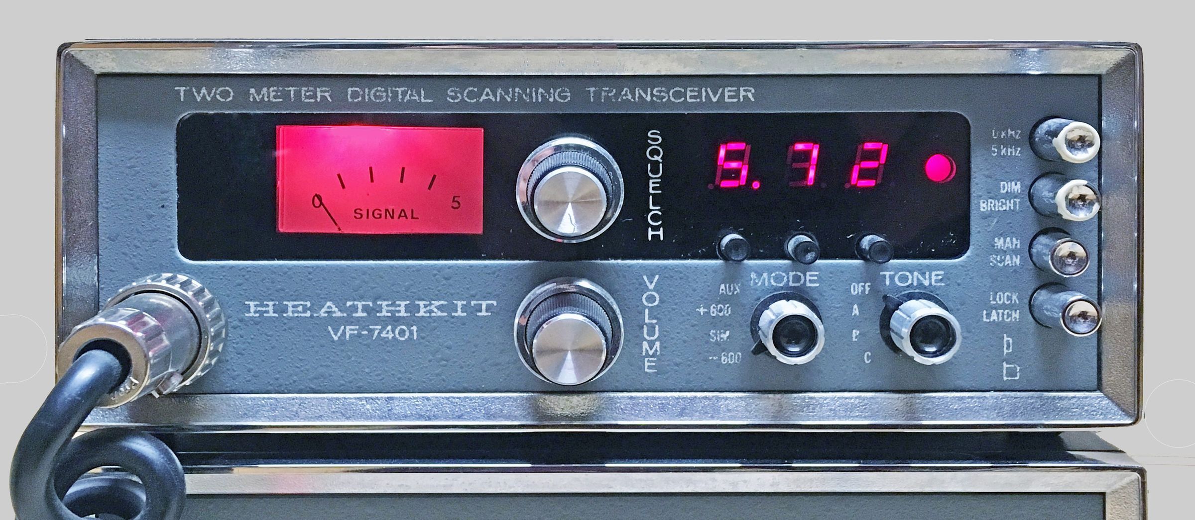
Three front panel push buttons allow you to enter any frequency you want, and the unit can be wired to power up on a pre-programmed frequency of your choice. This frequency is chosen during assembly and can be rewired later. There is also a front panel switch to select an offset of +600 kHz, –600 kHz, +1 MHz, or simplex.
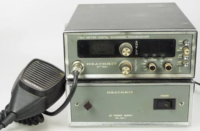
The VF-7401 covers any 4-MHz segment between 143.5 and 148.5 MHz with a rated power output of 15 watts. Heath advertised that the output power was continuously variable. Strictly speaking, that is true. However, it is variable only from a control on the power amplifier circuit board which is inaccessible without removing the cabinet. So for all practical purposes, it is not adjustable. The radio is built on six PC boards and borrows heavily from its predecessor, the HW-2036.
The receiver features a double-tuned front end with an RF amp, dual-conversion, an 8-pole crystal IF filter, IC limiting, and quad detection.
Receiver sensitivity is better than 0.5 µV. Bandwidth is 6 dB down at 15 kHz. All birdies are less than 1.0 µV equivalent. Heath advertised that the synthesizer had been substantially improved and no longer required a front panel indicator to tell you it’s locked on frequency. Heath did, however, put a PLL lock indicator light inside—just in case.
The transmitter is protected from high SWR and has a 100 percent duty cycle. Deviation is adjustable from 0-7 kHz. Mobile users may wish to note that the operating temperature range is from +15 to +125 F. Depending on where you live, these limits could easily be exceeded in your car.
The 7401 features a CTCSS (PL) tone encoder. The user can choose from three tones via a front panel switch. Tone frequencies are selected during assembly.
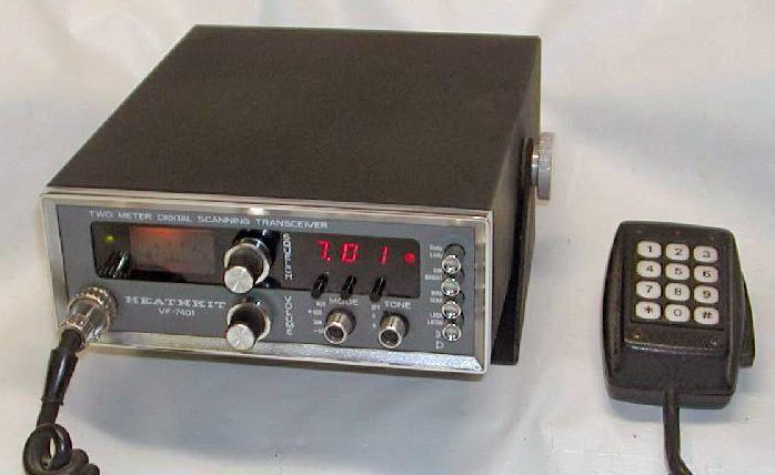
Front panel controls include volume, squelch, offset, tone, scan mode, scan/manual, display brightness, a 5 kHz select, and three tuning buttons—1 MHz, 100 kHz, and 10 kHz. The front panel also features a red LED indicating 5 kHz selection, a green LED indicating a unsquelched or “channel busy” condition, and a three digit LED frequency display.
Unlike the HW-2036, the mic on the VF-7401 is detachable. The mic connector is a standard 4-pin DIN connector.
Rear panel includes power amp tuning, power level controls, a 12 VDC power connector, an external speaker jack, and an SO-239 antenna connector.
The VF-7401 was regarded as a difficult kit to build. Variations in paint color from green to blue to gray.
References:
Review. QST. Nov 1981, p. 43.
Programmable power-up freq mod. CQ. Jul 1983, p. 40.
RECEIVER
Sensitivity: 15 db of quieting at 0.5 µV
Squelch threshold: 0.3 µV or less
Audio output: 1.5 watts at less than 10% THD; 2 watts maximum output (typical)
Image rejection: –50 db or greater
Spurious rejection: –50 db or greater
IF rejection: –80 db or greater
Internally generated spurious signals: below 1 µV equivalent
Bandwidth: 6 db at 15 kHz minimum, 60 db at 30 kHz maximum
Modulation acceptance: 6 kHz minimum
TRANSMITTER
Power output: adjustable (10 to 15 watts nominal) into a 50Ω resistive load (13.8 VDC, 25C)
Spurious and harmonic output: –60 db
Modulation: FM, 0 to 7 kHz, adjustable
Duty cycle: 100% with less than 10:1 SWR
Tone encoder: 3 tones, 70 to 200 Hz, approximately 700 Hz deviation
Transmitter offset: –600 kHz, +600 kHz, + 1 MHz, (AUX)
GENERAL
Frequency coverage: any 4-MHz segment between 143.5 and 148.5 MHz
Frequency increments: 5 kHz
Frequency stability: ±0.0015%
Operating temperature range: +15F to +125F
Power requirements:
12.6 to 16 VDC, 13.8 nominal
receive current: 550 mA squelched, 750 mA at full audio
transmit current: 4 amps maximum at 13.8 VDC
Photos, general information and specifications from "Heathkit: A Guide to the Amateur Radio Products," by Chuck Penson, WA7ZZE. Used with permission.