Note
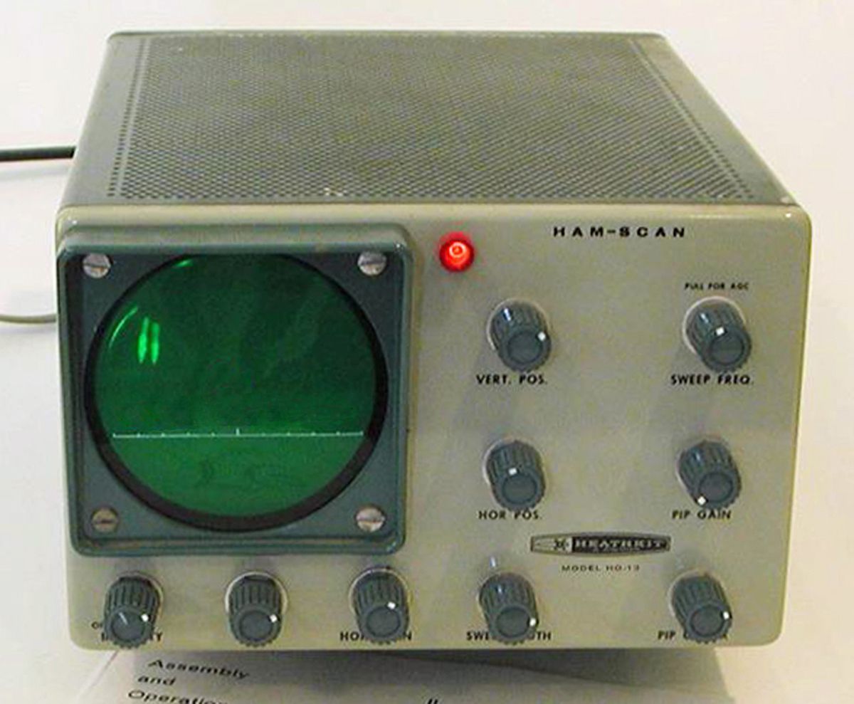
The HO-13 provides a “picture” of band activity up to 100 kHz wide. Signals are displayed as pips on the screen, and their positions left or right of the center of the screen can be interpreted as their frequency in kilohertz higher or lower than where your receiver is tuned. As you tune the receiver, the pips move slowly across the screen. The signal you hear is always in the center of the screen.
The value of such a gizmo depends to a certain extent on your fondness for gadgets. The advantages, however, are clear. It is possible, for example, to identify clear frequencies in a band without having to tune around, to get an idea of general band conditions, to spot activity on a “deserted” band, and identify transmission modes and signal strengths of signals not tuned in.
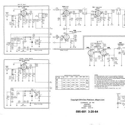
The HO-13 uses point-to-point wiring and is built around seven tubes (excluding the CRT). The low voltage power supply is solid state. Connection to the receiver is through a small value capacitor to the plate of the first IF stage.
Important: The HO-13 must be wired for a particular receiver IF frequency. The unit originally was supplied with all the parts needed to make it work with the following IFs: 455, 1600, 1650, 1681, 2075, 2215, 2445, 3000, 3055, and 3395 kHz (the SB and HW series IF). To rewire for a new IF will require the right parts and the manual. While the manual may be easy to find, finding the right parts may not, especially coil L2.
Sensitivity is about 50 µV for one inch of vertical deflection. Frequency scan width is approximately 30 to 100 kHz and is continuously variable. Resolution is approximately 2 kHz. Using the HO-13 takes some practice, but once you become comfortable with it, it can be a very useful accessory.
The HO-13 was supplied with a 3RP1 CRT and green reticle, though units are occasionally found with a user installed 3RP7 high persistence CRT and yellow reticle Heath used later in the SB-620. The reticle over the tube is a single horizontal line with ten divisions. The unit is housed in a two-tone green cabinet with a dark green bezel and matches the HO-10, TX-1, et al.
The HO-13 is easily overlooked because it is nearly indistinguishable from the matching HO-10.
In 1966 the HO-13 was refined, put into an SB style cabinet and released the SB-620.
Warning: Lethal voltages present when operating. Caution: Handle cathode ray tubes (CRTs) with great care.
References:
Review. Electronics World, Aug 1964, p. 68.
Review. QST. Nov 1964, p. 54.
Review. 73 Amateur Radio. Sep 1965, p. 70
Review. CQ. Sep 1965, p. 57.
Input frequencies (receiver IF): one of the following: 455, 1600, 1650, 1681, 2075, 2215, 2445, 3000, 3055 and 3395 kHz
Frequency response: ±0.5 db @ ±50 kHz from receiver IF
IF: 350 kHz
Sensitivity: 50 µV signal provides about 1 inch of vertical deflection with gain set at maximum
Sweep frequency: 10 to 50 Hz, variable
Sweep width: from less than 30 kHz to 100 kHz ±20%, continuously variable (from about 15 kHz to 100 kHz for 455 kHz)
Resolution: 2 kHz (frequency difference between two 1-inch pips whose adjacent 3 db points are coincide); Measured at 30 kHz width at lowest sweep speed
Power requirements: 120 VAC, 50/60 Hz, 40 watts
Tubes: (1) 6AT6, (1) 6EW6, (1) 6C10, (2) 6EW6, (1) 6EA8, (1) 1V2, (1) 3RP1 CRT.
Photos, general information and specifications from "Heathkit: A Guide to the Amateur Radio Products," by Chuck Penson, WA7ZZE. Used with permission.