Note
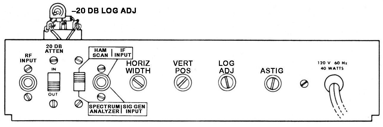
Announced in fall/winter 1966 with "expected availability April 1967." In catalog for sale March 1967. When considering the purchase of an SB-620, the most important thing to know is the IF frequency for which it has been wired. See Figures 1, 2, and 3 for details.
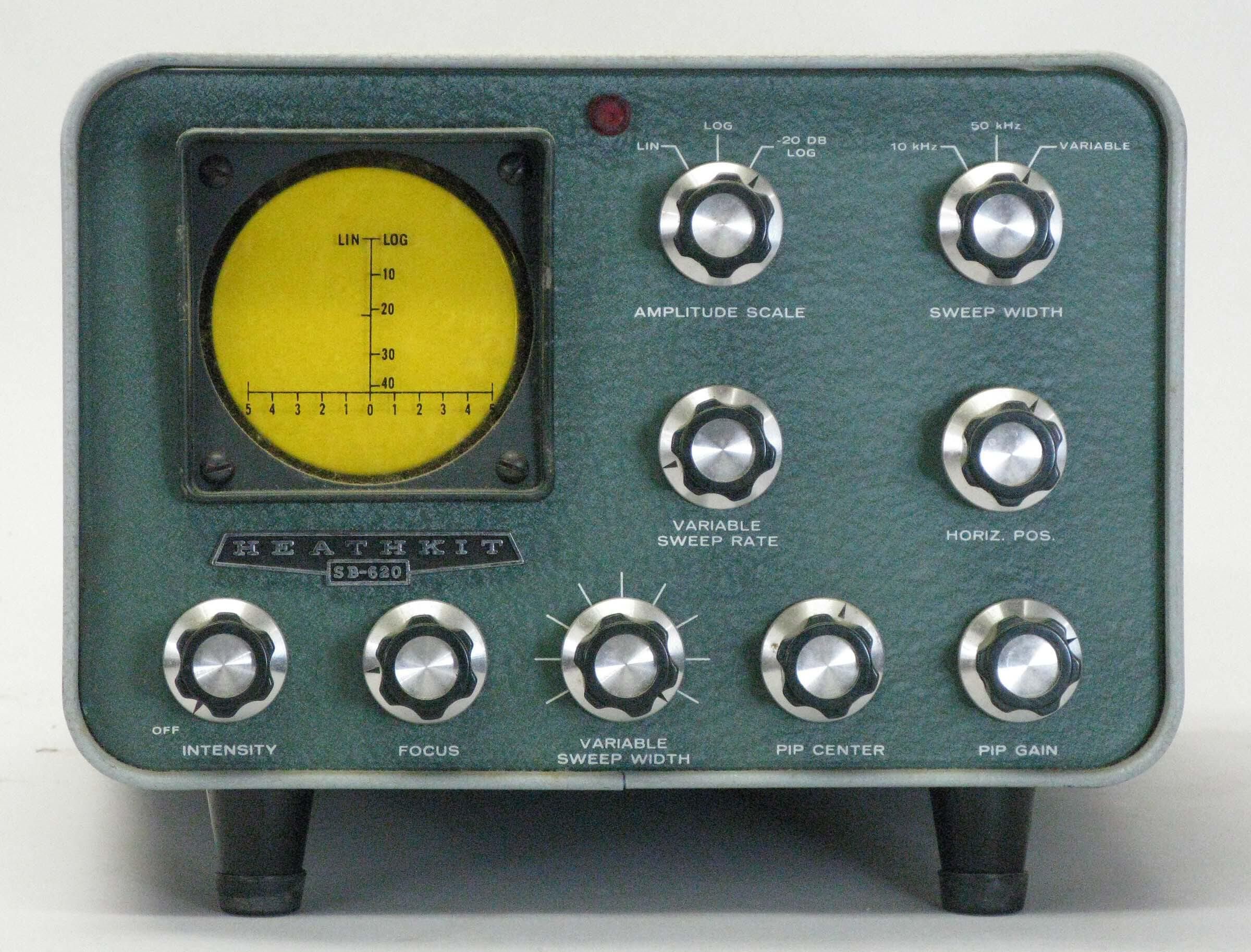
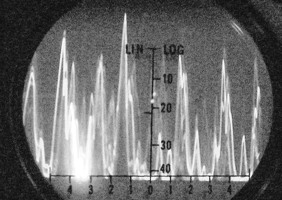
Easy to spot at a distance because of its bright yellow CRT, the SB-620 is an updated and refined version of the HO-13. Like the HO-13, the SB-620 is designed to provide a visual presentation of the band to which you are tuned. The 620 will present a portion of the band as wide as 500 kHz to as narrow as 10 kHz, depending to some extent on the IF frequency for which it has been wired. The presentation is centered on the frequency your receiver is tuned to, and allows you to “see” up and down the band. Signals appear along a calibrated line as “pips” on a high persistence CRT. The SB-620 is particularly useful in spotting band openings and for finding clear spots in a crowded band. With some practice the user can determine not only the frequency of signals elsewhere on the band, but their strengths and emission types as well. The 620 also can be used as a spectrum analyzer, but this use will not be described here.
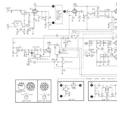
The 620 is built around six tubes (excluding the CRT), and has a built-in solid state power supply. All wiring is point-to-point.
Because they are subjected to high voltages, resistors in the intensity, focus, horizontal, and vertical position circuits will degrade over time, usually drifting up in value. The result will be the inability to effectively control one or more of these functions. This is a common ailment in SB-620s but one that is easy to fix.
The filaments of three tubes, V1, V2, and V5 are run on DC to prevent any AC hum from getting into the circuits. The DC is provided by a full wave bridge. It is worth checking to ensure that the circuit is still providing a nominal 6.3 volts under load.
The 3RP7A CRT may be difficult to find, but there is no functional reason that it can’t be replaced with a standard persistence 3RP1A (as found in the SB-610 and 614 and several pieces of Heathkit test equipment). The “A” version of these CRTs is preferred as it has a flat face.
The 620 also uses a pair of not-so-easy-to-find NE-83 neon lamps. Note that an NE-2 or other neon bulb will not suffice as a replacement. One is used in the sweep generator and the other is used as a voltage regulator that doubles as the pilot light.
The alignment procedure is not complicated but does require a high-quality RF generator and an accurate audio generator. The Heath IG-42 or IG-102 RF generators, and the Heath IG-72 audio generator would be ideal for this purpose.
Heath discontinued the SB-620 in 1976 and it wasn’t until 1988 that another panadapter was released—the HO-5404 monitor scope (the panadapter module was optional).
The SB-620 actually works very well and enjoyed moderate success. Still highly sought after.
Warning: Lethal voltages present when operating. Caution: Handle cathode ray tubes with great care.
Power requirements: 120/240 VAC, 50/60 Hz, 40 watts
Tubes: (1) 6AT6, (1) 6AU6, (1) 6EA8, (2) 6EW6, (1) 12AU7,
(1) 3RP7A CRT (functionally identical to 3RP1A)
Photos, general information and specifications from "Heathkit: A Guide to the Amateur Radio Products," by Chuck Penson, WA7ZZE. Used with permission.