Note
DX-100 1955-1957 $189.50
DX-100B 1957-1961 $189.95
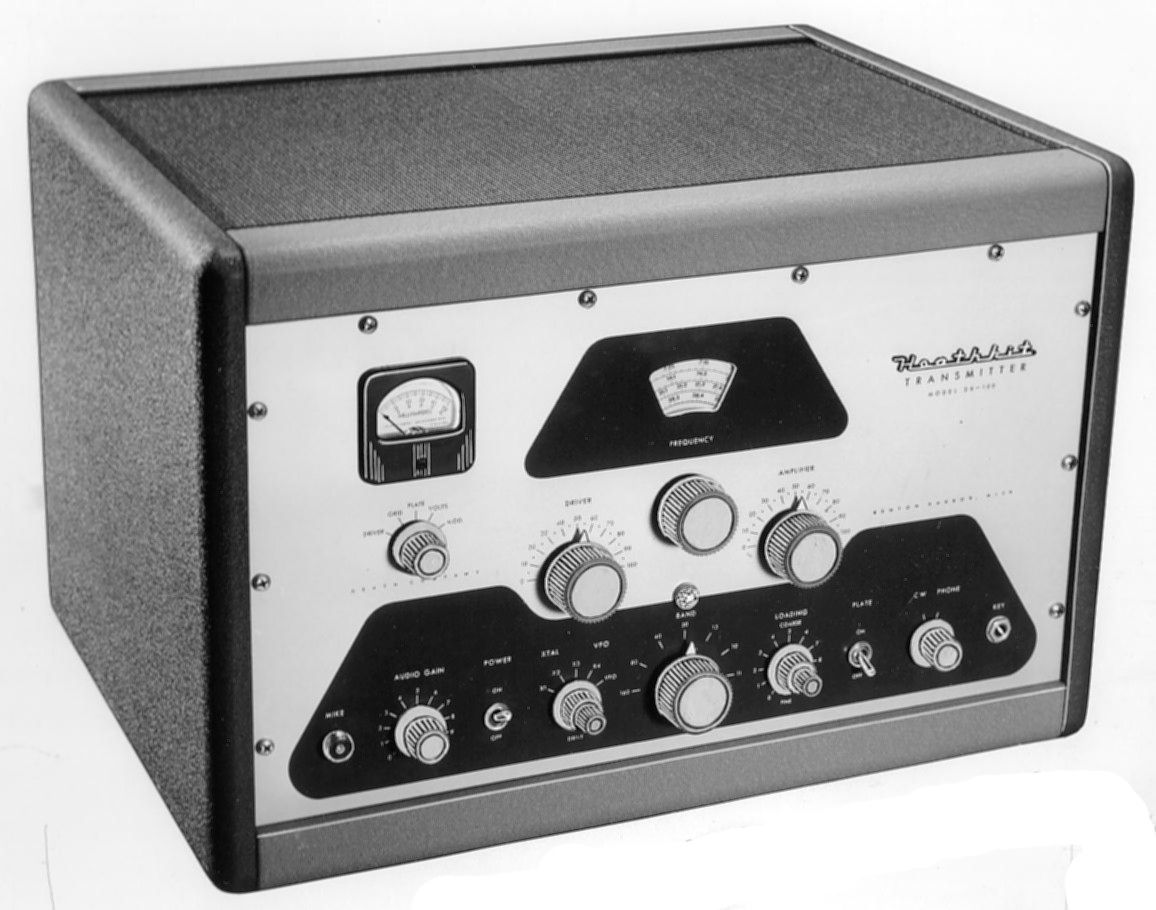
The two-tone gray DX-100 and 100B (there was no A version) were the first of Heath’s big guns and the first in the DX series. They were immensely popular. At 100 pounds, these massive 15-tube transmitters were typical of the era.
The DX-100 is built on a copper-plated chassis with a clear lacquer coating; the B version is built on a zinc-plated chassis with no coating. Both versions feature a built-in illuminated VFO (identical to the one used in the VF-1), modulator, power supply, and illuminated PA meter (basic movement 1 mA, 47Ω). Both the original and the B are rated at 100+ watts AM (plate modulated) and 120+ watts CW, and cover from 160 through 10 (including 11) meters. They use push-pull 1625s in the modulator and a pair of 6146 finals. The 6146 had just come onto the market and Heath quickly settled on it as the amplifier of choice, using it in most future transmitters. The 100 and 100B also used Pi-network interstage and output coupling.
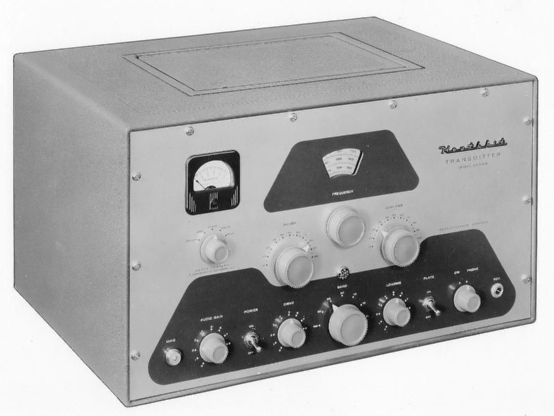
There are some significant differences between the 100 and 100B. The 100 provides for selection of four crystals or the VFO from a switch on the front panel. In the B version there is only one crystal available—from a switch inside the cabinet. The 100B is pre-punched for an additional SO-239 (not included) for those wanting to modify it for use with the SB-10 SSB adapter.
The DX-100 uses a combination of stepped loading (for coarse adjustment) and variable capacitor loading (for fine tuning). This scheme was replaced in the 100B with a larger gear-driven variable cap less prone to arcing; a modification kit was offered for DX-100 owners.
Also, there are subtle changes in the styles of the knobs. The DX-100 knobs used white lines for pointers. On the 100B the pointers are little white triangles.
The most obvious change in the B version is the cabinet. The multi-piece cabinet of the 100 was replaced with a one-piece formed cabinet with a hatch in the top, through which one gains access to the crystal and makes other adjustments.
There also are some minor changes in the loading and crystal circuits and in the output circuit. The 100 and 100B will match from 50 to 600Ω. See Figures 2 through 5 for front panel differences.
The DX-100B was last advertised in QST magazine in March 1960, but an assembly manual for the DX-100B dated November 1960 shows the unit with a plastic meter, instead of the familiar bakelite. See Figure 5. Because an illustration of this style of meter was also found within the step-by-step instructions, it is possible that a handful of units with the meter variant were delivered very near the end of production. As of this writing, a DX-100B with such a meter has not been found.
OFFICIAL MODIFICATIONS
Heath released three official modifications for the DX-100.
Modification MK-1 provides for SSB operation of the DX-100 or DX-100B in conjunction with the SB-10 sideband adapter. This involved some wiring changes, an additional SO-239 connector and installation of a bracket containing a potentiometer and two 0B2 regulator tubes. This assembly is located on the underside of the chassis, near the 5V4 rectifier socket. The modification also required the addition of a front panel switch located beneath the Heathkit logo. A decal, supplied with the modification, reads “AM-CW SSB” and was to be affixed to the front panel above the switch. See entry for SB-10 for additional discussion.
The second modification, MK-2, is inferred by the gap between MK-1 and MK-3. While instructions for MK-1 and MK-3 are clearly titled as such, the instructions for the MK-2 modification are not. Instead, this modification is titled “Improved Keying for the DX-100.” As of this writing, a modification labeled clearly as MK-2 has not been found. It is generally assumed that MK-2 is the modification designed to fix a problem with key clicks and chirp. The mod involved, among other things, the installation of a front panel pushbutton switch below the Heath logo. This modification was originally published in the August 1956 edition of QST magazine, and was authored by Heath’s chief engineer, Roger Mace.
MK-3 replaced the fixed and variable loading of the DX-100 with a single variable capacitor, as found in the DX-100B.
OCTAL SOCKET
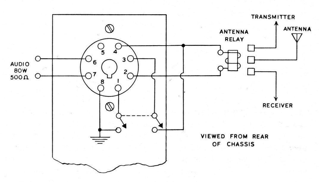
Refer to Figure 6. A rear panel octal socket is provided to duplicate the functions of the plate switch, and provides 120 VAC for an antenna relay and/or receiver mute relay when the plate switch is on. The socket is designed for use with the VX-1. In addition, audio output of up to 80 watts can be used for excitation of a higher power modulator, but this requires a modification of the DX-100(B). See the assembly manual for details (DX-100, page 57; DX-100B, page 59). Pin 8 provides and auxiliary ground in the event that shielded cable is used for remote operation.
The DX-100B was supplanted by the TX-1 in 1958, and discontinued in 1960.
References:
Review. QST. Dec 1955, p. 49.
Review CQ. Mar 1961, p. 36.
Notes. QST. Jun 1956, p. 77.
Improved keying. QST. Aug 1956, p. 34.
More keying hints. QST. Feb 1957, p. 59.
DSB for. CQ, Apr 1957, p. 54.
Better keying. CQ, Feb 1958, p. 34.
Break-in using a VR tube. QST. Sep 1958, p. 28.
SSB for. CQ. Feb 1959, p. 44.
Diode time-sequence keying. QST. Apr 1959, p. 35.
Correcting grid current. QST. Jun 1959, p. 62.
Improved keying. CQ. Apr 1959, p. 46.
SB-10 modification for. QST. Aug 1959, p. 53.
Audio circuit change. QST. Nov 1959, p. 55.
Improved keying and drive. QST. Feb 1960, p. 50.
Adding VOX. CQ. Aug 1960, p. 54.
Adding VOX (correction). CQ. Oct 1960, p. 26.
Tips. CQ. Jan 1961, p. 71.
Modification references. CQ. Feb 1961, p. 68.
Final modification. CQ. Aug 1961, p. 96.
High modulator stand-by current. QST. Aug 1962, p. 56.
FSK, reference only. CQ. Aug 1962, p. 95.
Modifications. QST. Sep 1962, p. 34.
RF output indicator. CQ. Jul 1963, p. 58.
HV rectifier arcing. QST. Jul 1964, p. 81.
Fuse blowing problems. CQ. Nov 1964, p. 113.
Rectifier replacement (brief). CQ. Mar 1965 , p. 67.
Keying. QST. Feb 58, p. 69.
Use with Johnson 6N2. CQ. May 1969, p. 83.
TVI problems. CQ. May 1970, p. 80.
Improved stability for RTTY. CQ. Jun 1972, p. 12.
Keying modification. QST. Aug 1977, p. 49.
Keying modification (correction). QST. Sep 1977, p. 51.
Antenna network that covers 160 m. QST. Dec 1977, p. 46.
Review. Electric Radio. Jun 2006
More drive. Electric Radio. Jan 2008.
Marriage of a DX-100, TX-1 and FT-101. Electric Radio. Jan 2009.
Upgrades. Electric Radio. Jul 2009.
RF power output: 100-125 watts AM, 120-140 watts CW
Output impedance: 50-600 Ω
Output coupling: Pi network (coaxial)
Operation: Crystal-VFO, CW-AM, local-remote
Band coverage: 160, 80, 40, 20, 15, 11, 10 meters
Modulator output: 85 watts, 300 to 3000 Hz
Power requirements: 120 VAC, 50-60 Hz
standby: 150 watts
CW: 400 watts (intermittent)
AM: 450-600 watts
Size-Weight:
DX-100: 21 wide x 13.75 high x 16 deep; 100 lbs
DX-100B: 19.5 wide x 11.5 high x 16 deep; 100 lbs
Tubes (DX-100 and DX-100B): (1) 6AL5, (1) 5V4, (2) 5R4, (1) OA2, (1)12AX7, (1) 12BY7, (2) 1625, (1) 6AU6, (1) 12BY7, (1) 5763, (2) 6146, (1) 6AQ5
Photos, general information and specifications from "Heathkit: A Guide to the Amateur Radio Products," by Chuck Penson, WA7ZZE. Used with permission.