Note
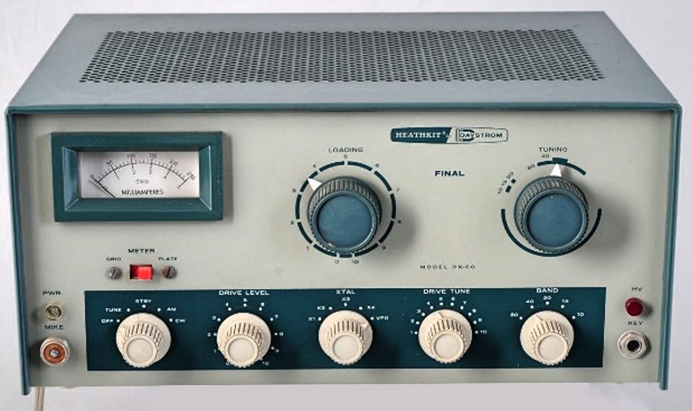
DX-60 1960-1964 $82.95
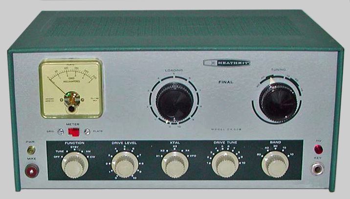
DX-60A 1965-1967 $79.95
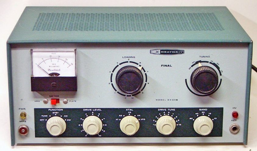
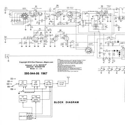
DX-60B 1967-1976 $79.95
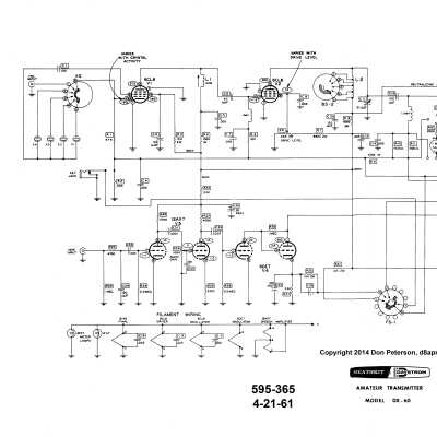
The DX-60 series was the last and most successful of the “DX” line—it was on the market for 16 years. Completely re-styled and wearing Heathkit two-tone green paint, externally the DX-60 bears no resemblance to its predecessors. Electronically there are a few similarities, but the DX-60 is much more than a DX-40 in a new box. First, the DX-60 uses a solid state power supply. And though the basic 5-tube audio and RF tube line-up is almost identical to the DX-40, the actual RF circuit is a return to that used in the DX-35—an electron coupled Pierce oscillator—with a number of distinct improvements. For example, the 6146 is now fully neutralized, and there is a pot for controlling the grid drive. The DX-60 also uses grid block keying and is rated at 90 watts AM using screen modulation (about 65 percent max.) and CW, 80 through 10 meters. The Pi-network output circuit is followed by a built-in low pass filter—a welcome feature, although the trade-off is that the unit will match loads only from 50 to 75Ω.
The front panel has a full range of controls, full metering, connectors for a mic and key, and two pilot lights (“ON” and “HV”). Other features include front panel selection of four crystals or an external VFO, and octal accessory socket provides power for a VFO and an external T/R relay.
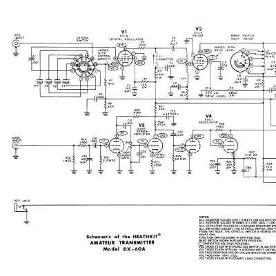
There are a number of differences between the DX-60 and the A and B versions. The most obvious are the external differences. For example the smooth paint finish of the original and A version was replaced with a wrinkle finish on the B.
Each version uses different style of meter. The recessed illuminated meter of the first version proved too costly and was replaced with a panel-mounted, non-illuminated type. On the A version, the meter most often has rounded corners and a yellowish face. On the B version, the meter usually has square corners and a black section covering the movement. Subtle variations in meter style have been seen in both the A and B versions, but the meter always says “Heathkit.” Very early B versions used A style meters.
On the DX-60, the crystal sockets were located on the rear panel. On the A and B versions the crystal sockets were moved to the rear deck. Originally, all four sockets were for use with FT-243 crystals. On the A and B versions one of the sockets (X1) was changed to accommodate an HC-6/U style crystal.
The DX-60 had a small box on the rear panel covering the entrance of the line cord. This was to accommodate a pair of bypass capacitors. On the A and B versions the capacitors were changed, obviating the need for the box.
The original DX-60 use a fused power plug. The A and B version use a internal self-resetting circuit breaker.
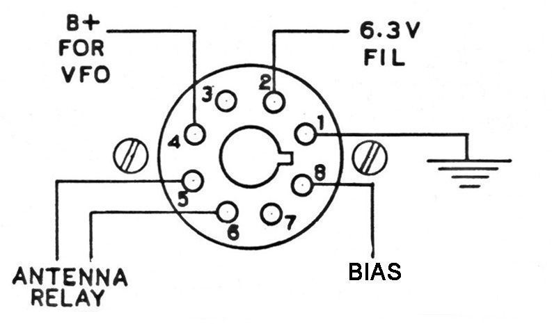
The accessory socket provides power for the HG-10(B) VFO, and for an external antenna relay. Pin 2 provides 6.3 volts at 4 amps on the DX-60 and 2 amps on the A and B versions. Pin 4 provides 300 volts B+ at 50 mA. Pin 8 provides –65 volts key up for grid-block keying of the HG-10(B) VFO.
Caution: When the transmitter is switched to either CW or PHONE operation, 120 VAC is applied to pins 5 and 6 for operation of an external T/R relay. Because the mode switch breaks only one side of the line, pin 6 is always hot. A shock hazard exists.
References:
Brief Description. Electronics World, Feb 1961, p. 129.
Brief description. Popular Electronics, Mar 1961, p. 38.
Review. QST. Jul 1961, p. 42.
New product announcement. CQ. Apr 1961, p. 80.
Hints. CQ. Feb 1963, p. 82.
Modulation problems. CQ. Jul 1962, p. 80.
Erratic keying. CQ. Sep 1962, p. 68.
Audio hum and distortion. CQ. Oct 1962, p. 65.
Drive/tune peaking on 80. CQ. Oct 1962, p. 65.
Fuse blowing problems. CQ. Oct 1962, p. 65
Only loads on 40. CQ. Oct 1962, p. 65.
Use with SB-10. CQ. Jan 1963, p. 74.
PTT. CQ. Jul 1963, p. 57.
Plate modulation tip. CQ. Dec 1964, p. 101.
Key clicks. CQ. Sep 1965, p. 51.
Burned out meter. CQ. Sep 1966, p. 88.
Use with tuner (very brief). CQ. Sep 1966, p. 90.
PTT with HQ-170A. CQ. Jan 1968, p. 117.
Straight-through VFO operation. CQ. Jan 1969, p. 85.
PTT. CQ. Oct 1970, p. 77.
Use with SB-640. CQ. Oct 1971, p. 79.
Use with Allied A-2516 receiver. CQ. Apr 1972, p. 10.
Use on 30 meters. CQ. Mar 1985, p. 90.
Band switch replacement. QST. Sep 1987, p. 43.
More switch replacement info. QST. Sep 1988, p. 48.
Notes on. Electric Radio. Mar 1998
Use on 160 meters. Electric Radio. Jan 2001.
Heising modulator. Electric Radio. Jan 2004.
CW modification. Electric Radio. Oct 2005, p. 197.
Revisiting. Electric Radio. Feb 2015.
Power input: 90 watts CW and controlled carrier AM.
Output impedance: 50-75Ω
Output coupling: Pi-network, SO-239
Band coverage: 80, 40 20, 15 and 10 meters
Power requirements: 120 VAC, 60 Hz, 225 watts
Tubes: (1) 12AX7, (1) 6DE7, (2) 6CL6, (1) 6146
Photos, general information and specifications from "Heathkit: A Guide to the Amateur Radio Products," by Chuck Penson, WA7ZZE. Used with permission.