Note
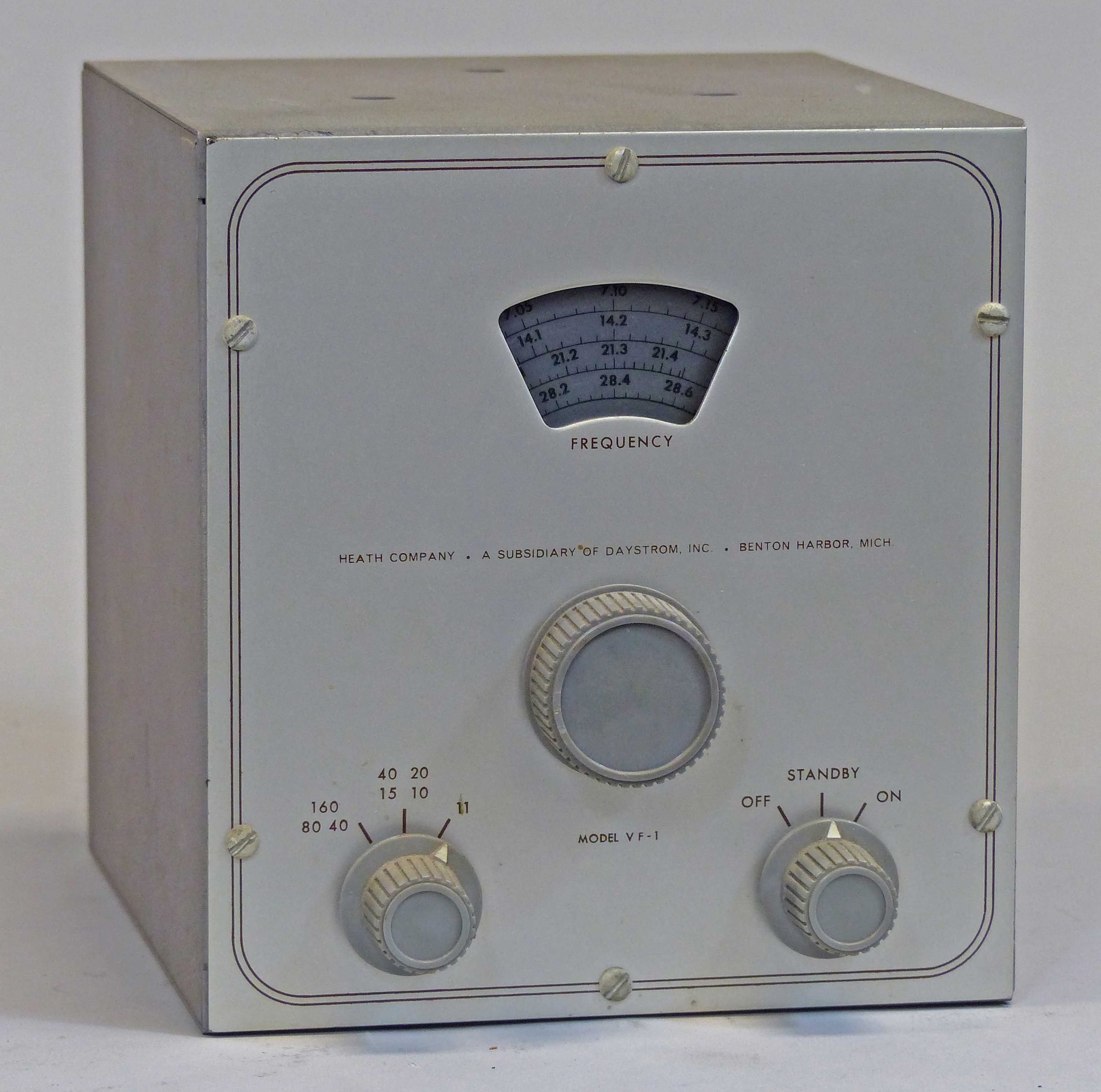
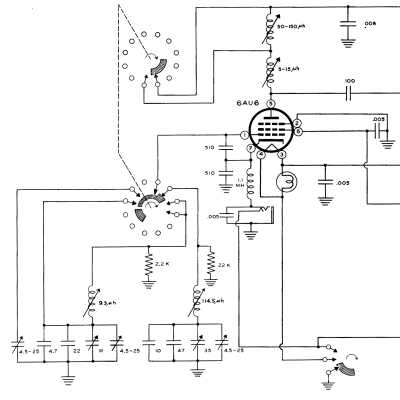
The VF-1 was Heath’s first external VFO and was released in 1954 as a companion unit for the AT-1, which had been released about a year earlier. The unit outlasted the AT-1 and later was sold for use with the DX-20, 35, and 40, although it could also be used with the DX-60 series and others. The VF-1 is the same VFO design used later in the DX-100. It covers 160-10 meters (including 11 meters) with three basic output frequency ranges and provides about 10 volts of RF drive. It uses two tubes: an 0A2 and a 6AU6. The oscillator is an electron-coupled Clapp type (a series tuned Colpitts).
Operation on 6 and 2 meters is possible by adjusting the 11 meter padding capacitor down to 6 MHz. With suitable doubling, six-meters can be worked with the 8th harmonic, and 2 meters may be operated on the 24th harmonic of the VFO. Obviously, any drift will show up right away.
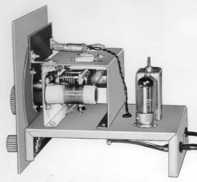
The unit features an illuminated dial, copper plated chassis, aluminum case, “profuse shielding,” ceramic coil forms and switch wafers, and tuning capacitor insulation. The tuning vernier reduction drive provides about two feet of bandspread. There is no built-in power supply. The VF-1 is designed to take its power from the transmitter.
Stability of the VFO is achieved by various means including coils wound on heavy ceramic forms using Litz wire, and coated with Q-max and baked. The tuning capacitor uses double bearing construction, with coils and the capacitor mounted on a sub-assembly and isolated from the main front panel. All of the frequency determining components including the padding and temperature compensating capacitors are mounted in a separate compartment so that they all are operating at the same temperature. The series tuned Colpitts oscillator is also inherently more stable than other designs. Still, many users further minimized drift by building a power supply that would keep the VF-1 powered up all the time (as in the DX-100).
Front panel controls include main tuning, band switch, and off-standby-on. There are two cables on the rear panel: power in and RF out. The VF-1 is painted in a two tone gray to match the AT-1. The knobs are gray and are the same style used on the DX-20, et al.
Plug and play operation with the AT-1, DX-20, DX-35 and DX-40. Use with the DX-60 series requires a modification of the VFO. Refer to DX-60 for details.
References
Use with AT-1 on 15 meters. QST. Apr 1955, p. 50.
Connected to antenna, used as transmitter (Strays). QST. Feb 1959, p. 55.
Driving the AT-1 on 15 meters. QST. Jun 1959, p. 62.
Use on 14 MHz MARS freqs. QST. Nov 1959, p. 55.
Use on 6 & 2. CQ. Feb 1960, p. 59.
Modification to stabilize. QST. Mar 1964, p. 64.
New life for. QST. Dec 1972, p.18.
Use on 30 meters with DX-20. QST. Jan 1986, p. 49.
Output frequencies:
1750-2000 kHz
7000-7425 kHz
6740-6808 kHz
Calibrated bands: 160, 80, 40, 20, 15, 11 and 10 meters
RF output: about 10 volts
Power requirements: 250-350 VDC @ 15-20 mA, 6.3 VAC @ 0.45 amps
Photos, general information and specifications from "Heathkit: A Guide to the Amateur Radio Products," by Chuck Penson, WA7ZZE. Used with permission.