Note
SB-110 1965-1969 $360.00
SB-110A 1969-1971 $319.95
Looking very much a like a mirror image of the SB-100, the SB-110 was actually on the market about six months before the SB-100. The SB-110(A) uses the same tube type LMO as the SB-100 (see SB-100 listing for a discussion of the LMO), and its specifications are also similar. The SB-110 will operate USB, LSB and CW. As in the SB-100 series, the CW is VOX operated and uses grid block keying.
The SB-110(A) is built on five PC boards (six if you count the tiny ANL board) and uses 17 tubes including a pair of 6146 final amplifiers and a pair of 6DS4 Nuvistors. A single transistor is used as well, in the audio amplifier.
The transceiver will tune four 500 kHz band segments between 49.5 and 54 MHz and comes standard with crystals for coverage from 50 to 52 MHz, and front panel control callouts to match.
The receiver section is a triple conversion superhet using Heath’s standard IF frequencies. There are provisions for only one filter (the SSB filter was standard equipment).
Features include switch selection of USB, LSB, and CW, as well as PTT and VOX operation. In addition the SB-110(A) features ANL, AGC, a built-in sidetone, and a built-in 100 kHz crystal calibrator. Note that calibration of the calibrator is critical since a 5 Hz error at 100 kHz will translate to a 2.5 kHz error at 50 MHz.
Crystal control is provided for Military Affiliate Radio Service (MARS) or net operation. The SB-110(A) can transmit on the crystal frequency while the LMO tunes the receiver, or can be made to transceive on the crystal frequency. Refer to discussion below under CRYSTAL OPERATION.
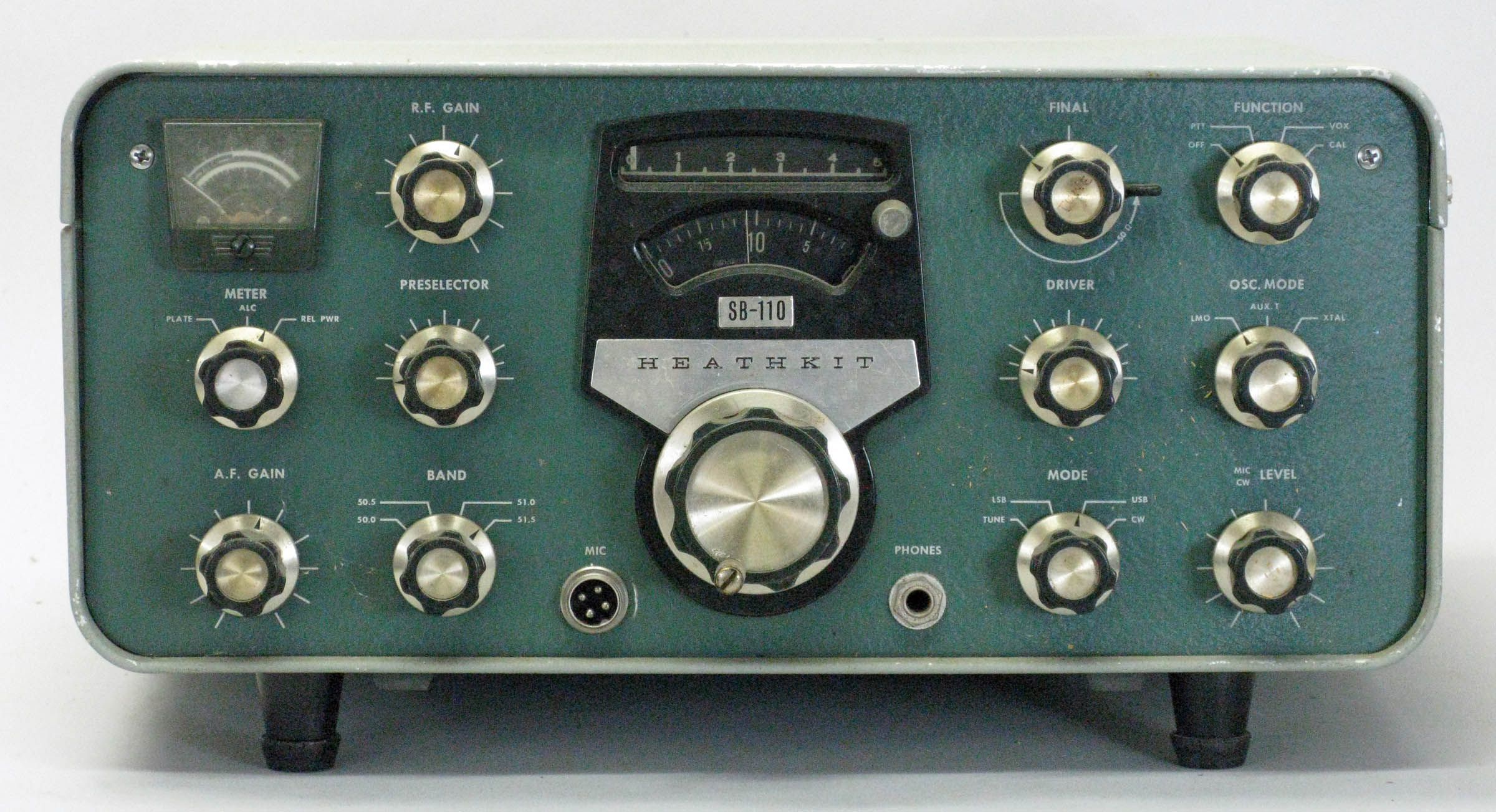
Front panel controls include main tuning, zero set, meter function, AF gain (pull for ANL), RF gain, preselelector, band, final tune, driver, mode, function, oscillator mode, and MIC/CW level. The mic and headphone jacks are on either side of the main tuning control.
Internal chassis mounted controls include VOX controls (near the final cage), headphone level, S-meter zero adjust, relative power meter adjust, sidetone level (right of the LMO), driver neutralizer (next to V13)), carrier null and balance (to the right of V9), bias adjust (left of the LMO), and ALC meter adjust (near V4).
A rear panel switch labeled ANT makes it possible to use a linear amplifier that does not have a built-in antenna change-over relay, for example. Another use would be in providing a separate antenna for receiving.
In addition to an 11 pin power plug, rear panel connections include RCA jacks for 50Ω RF output, receiver input, 8Ω speaker, phone patch, ALC, and a spare. The key jack is a standard quarter-inch connector.
Differences in the 110A include improvements in bypassing and filtering, and an improved (but still tube-type) LMO. The modifications were made to eliminate a signal being radiated by the heterodyne oscillator—present even in the receive mode. This signal was getting into TV channel 6.
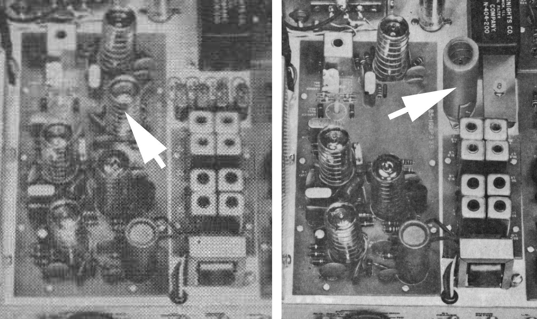
The front panel of both the SB-110 and 110A are labeled simply as SB-110, but it is not difficult to distinguish one from the other. Just look for the blue and white series plate, usually found on the rear apron. If the series plate cannot be located, refer to Figure 4 and note the location of tube V7, and other component location changes.
The SB-110 and early versions of the SB-110A used the same 404-200 SSB crystal filter found in the SB-100. Later versions of the SB-110A (probably 1967 and later) used the smaller 404-283 SSB filter, also used in the SB-101. Refer to Figures 1, 2, and 4 for examples of these filters.
The SB-110(A) is designed for use with the HP-23 and HP-13 series power supplies.
Heath (and a QST reviewer) noted that this was a challenging kit recommended only for those with previous kit building experience.
Caution: Be sure to use the +250 volt tap (or switch position) on the HP-23 and HP-13 series power supplies. Using the 300 volt setting will cause erratic operation in the SB-110(A).
CRYSTAL OPERATION AND FREQUENCY CALCULATIONS
There are three modes of operation:
LMO: the LMO controls both the transmitter and the receiver.
XTAL: the crystal controls both the transmitter and receiver.
AUX T: the crystal controls the transmitter while the LMO controls the receiver.
For USB operation: Fx = (Fc - Fh) – 3.3936
For LSB operation: Fx = (Fc - Fh) – 3.3964
Where:
Fx = crystal frequency
Fc = desired carrier frequency
Fh = heterodyne oscillator crystal, different for each band segment:
49.5 to 50.0 MHz 41.105 MHz (MARS operation, not supplied)
50.0 to 50.5 41.605 (supplied)
50.5 to 51.0 42.105 (supplied)
51.0 to 51.5 42.605 (supplied)
51.5 to 52.0 43.105 (supplied)
52.0 to 52.5 43.605 (not supplied)
52.5 to 53.0 44.105 (not supplied)
53.0 to 53.5 44.605 (not supplied)
53.5 to 54.0 45.105 (not supplied)
Note: The heterodyne oscillator crystals are located under a cover adjacent to the to crystal filter.
Crystal Characteristics
mode: fundamental
tolerance: 0.01%
holder: HC-6/U
load capacity: 15 µµF
internal capacity: 7 µµF
series resistance: 25Ω maximum
drive level: 2.0 milliwatts
References:
Review. QST. Feb 1966, p. 72.
Review. CQ. May 1966, p. 59.
Review (SB-110). 73 Amateur Radio Nov. 1965, p. 78.
Review (SB-110A). 73 Amateur Radio, Sep. 1968, p. 60.
Modification for AM. CQ. Nov 1966, p. 10.
AM operation. CQ. Aug 1967, p. 75.
Zero-set dial modification. QST. Feb 1980, p. 44.
General information about SB series. Electric Radio. Sep 2016.
RECEIVER SECTION
Sensitivity: 0.1 µV for 10 db signal-plus-noise to noise ratio
Selectivity: 2.1 kHz at 6 db down, 5 kHz maximum at 60 db down
Image rejection: 50 db or better
IF rejection: 50 db or better
Spurious responses: all below 0.1 µV, except at 51.250 MHz which is below 0.3 µV
Antenna input impedance: 50Ω
Audio output impedance:
speaker: 8Ω
headphones: 600Ω or higher
Audio output power: 1 watt
AGC: audio level varies less than 12 db for 50 db change of input signal (0.5 µV to 150 µV)
TRANSMITTER SECTION
DC input power:
SSB: 180 watts PEP
CW: 150 watts
RF power output (50Ω load):
SSB: 100 watts PEP
CW: 90 watts
Output impedance: 50Ω nominal with less than 2:1 SWR
Carrier suppression: 55 db down from rated output
Unwanted sideband suppression: 55 db down from rated output at 1000 Hz and higher
Distortion products: 30 db down from rated PEP output
Hum and noise: 40 db or better below rated carrier
RF compression (ALC): 10 db or better at 30 µA of final amp grid current
CW sidetone: about 800 Hz
Keying: grid block, VOX keyed with tone
Oscillator feedthrough or mixer products: 55 db below rates peak output
GENERAL
Frequency coverage: 49.5 to 54 MHz in 500 kHz segments (crystals supplied for coverage from 50.0 to 52.0 MHz
Frequency control: LMO or (one) crystal
Frequency stability: less than 100 Hz per hour after 20 minute warmup; less than 100 Hz drift for 10% supply voltage variations
Modes: USB, LSB, CW (800 Hz offset for cross-mode operation between USB and CW)
Dial accuracy:
electrical: within 400 Hz after calibration at nearest 100 kHz point
visual: with 200 Hz
Dial backlash: no more than 50 Hz
Calibration: every 100 kHz
IF:
1st receiver and 2nd transmitter IF: 8.395 to 8.895 MHz passband
2nd receiver and 1st transmitter IF: 3.395 MHz
Power requirements:
+700 VDC at 250 mA with 1.0% maximum ripple
+250 VDC at 100 mA with 0.05% maximum ripple
–115 VDC at 10 mA with 0.5% maximum ripple
12.6 VDC/VAC at 4.355 amps
Tubes: (1) 0A2, (1) 6BZ6, (4) 6EA8, (3) 6AX8, (1) 6CB6, (2) 6DS4, (1) 6EB8, (1) 12AT7, (1) 12BY7A, (2) 6146
Transistor: (1) 2N2712
Photos, general information and specifications from "Heathkit: A Guide to the Amateur Radio Products," by Chuck Penson, WA7ZZE. Used with permission.