Note
This over-designed amplifier was Heath’s first attempt at a linear, and was designed specifically with the TX-1 in mind. Although it was a good enough design and worked well, it was very short lived. Almost as soon as it was released (to favorable reviews), Heath realized that it probably had been a mistake. It was too much of everything. Too big, too heavy, and—most importantly—much too expensive to compete effectively.
Almost before the ink on the assembly manual was dry Heath started work to design a more compact and less expensive replacement—the HA-10.
The KL-1 itself was sold for less than a year, although its companion power supply (the KS-1) was released in June 1959—about six months prior to the KL-1.
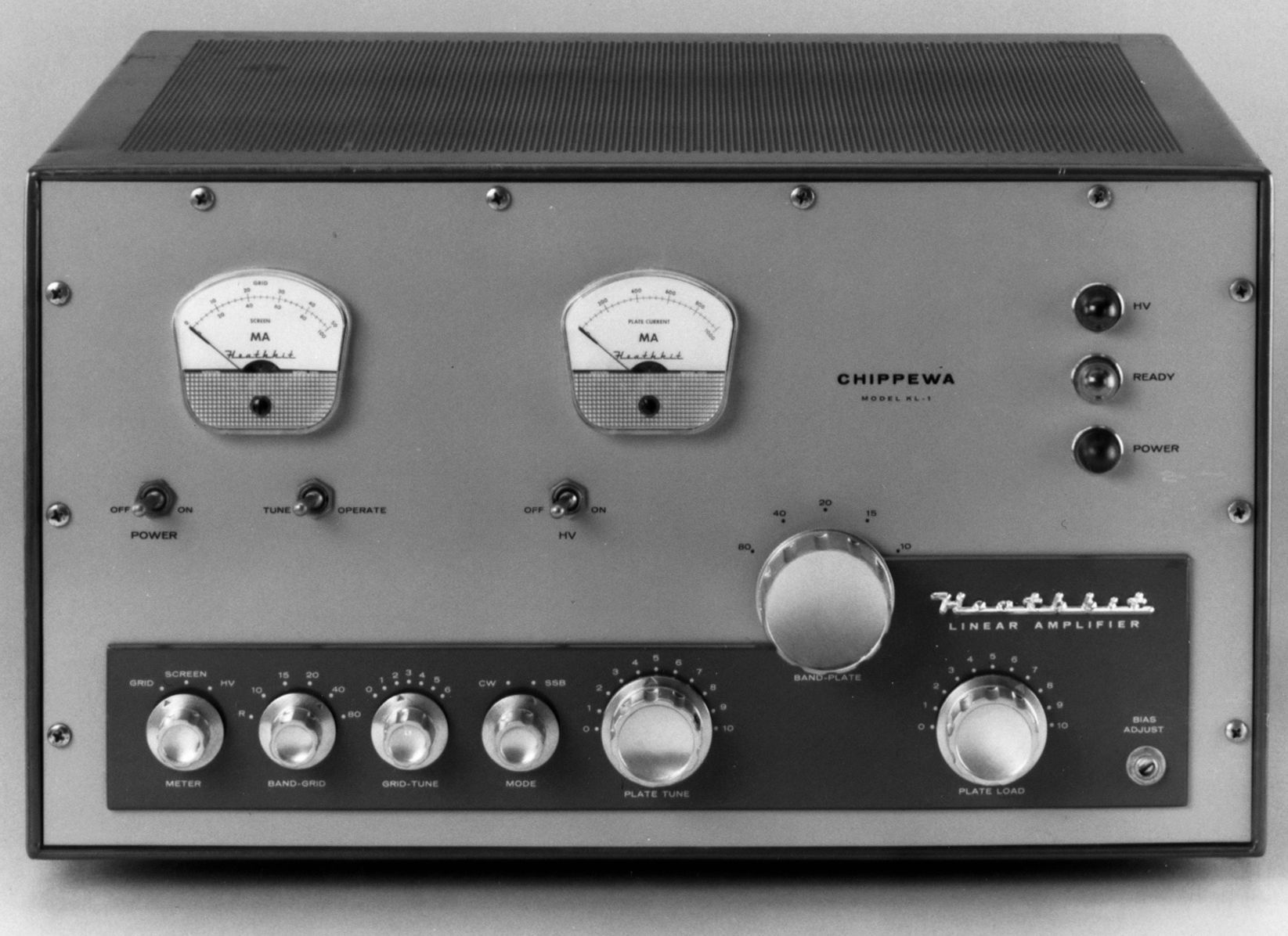
The KL-1 was designed to match the TX-1 transmitter and is the same size and color scheme of the TX-1. The unit covers 80-10 (but not 11) meters and can run class AB1 for SSB or AM (or CW) or class C for CW only. In AB1, the amp can be run with tuned or untuned input circuits depending on how much drive is available.
In the tuned configuration drive power may be as low as 10 watts, peak. With untuned input at least 60 watts of drive is required. Class C operation requires at least 40 watts of drive. Class AB1 output power is about 900 watts PEP, about 300 watts on AM, and about 750 watts (class C) CW.
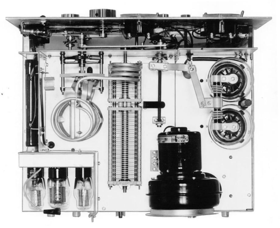
The KL-1 uses a pair of 4-400s and 7 other tubes. Features include forced air cooling, quarter inch silver-plated copper tubing in the final tank coil, full metering, and a heavy-duty plate parasitic choke assembly.
The pi-network output coils are silver plated copper tubes at 21 and 28 MHz. The ten-meter section of the coil is oriented in such a way that it will not couple to the rest of the assembly. An interesting feature is the tank capacitor. Two capacitors (50 pF and 150 pF) are used. At 14 MHz and below these two units are shorted together at the stators by a specially designed spring loaded contact system driven by the band switch.
A small pickup coil located near the tank coil provides a sample of the RF for viewing on an oscilloscope. A short coaxial cable routes the signal to a connector on the rear panel.
AB1 screen voltage is provided through a series of dropping resistors and is regulated at 800 VDC by six voltage regulator tubes. These tubes, and the resistors, are mounted horizontally in a compartment at the right rear of the chassis, along with a 6DQ6 clamp to control the screen circuit in class C operation.
Front panel controls include main power, meter function, grid band switch (selects tuned or untuned in-put), grid tuning, mode switch, bias, and final loading. There are two front panel meters. One reads plate current; the other may be switched between grid current, screen current, and plate voltage.
Adjustable negative bias for the control grids is provided by a full-wave power supply using silicon diodes.
The KL-1 derives its basic power from the KS-1 power supply. In spite of its obvious bulk, the KS-1 generates only the 3000 VDC high voltage. Filament voltage for the 4-400s as well as bias voltage are derived onboard the KL-1. All voltage regulation is done onboard the KL-1 as well. In addition to high voltage, the KL-1 also must have a source of 120 VAC for its filament and bias supplies. This is normally supplied from the KS-1 via a six-wire control cable between the two units.
Rear panel connections include an octal plug for connection to the KS-1, a high voltage connector for the KS-1, SO-239s for RF in and out, a scope output, a ground lug, and a octal socket for connection to the TX-1 and SB-10.
The KL-1 is exceptionally rare in any condition.
Although deleted from the catalog early in 1961, the KL-1 appeared once more in a discontinued-item sale flyer mailed in April 1962, but without it’s companion KS-1 power supply.
Warning: The entire 3000 volts of B+ appears at the meter. Use extreme caution when working in this area. Adjust the meter with an insulated screwdriver only.
Warning: Lethal voltages present while operating.
References:
Review. QST. Jul 1960, p. 42.
Review. Electric Radio. Feb 1998
Driving Power Required (measured at input connector on 10 meters)
Class AB1 (tuned grid): 10 watts (less at lower frequencies)
Class C (tuned grid): 40 watts (less at lower frequencies)
Class AB1 (swamped grid): 60 watts (same on all frequencies)
Input power:
Class AB1 (SSB voice modulation): 2000 watts PEP
Class AB1 (SSB two-tone test): 1300 watts
Class AB1 (AM linear): 1000 watts
Class C (CW): 1000 watts
Power output (20 meters):
Class AB1 (SSB voice modulation): 900 watts PEP
Class AB1 (SSB two-tone test): 550 watts
Class AB1 (AM linear): 300 watts
Class C (CW): 750 watts
Output impedance: 50 to 72Ω (unbalanced)
Input impedance:
tuned grid: 50 to 72Ω (unbalanced)
swamped grid: 170Ω (unbalanced)
Band coverage: 80, 40, 20, 15, 10
Power requirements:
AC: 120 volts, 50/60 Hz, 250 watts
DC: 3000 volts, 450 mA
Tubes: (2) 0C3, (4) 0D3, (1) 6DQ6, (2) 4-400A
Photos, general information and specifications from "Heathkit: A Guide to the Amateur Radio Products," by Chuck Penson, WA7ZZE. Used with permission.