Note
SB-200 1964-1978 $200.00
SB-201 1978-1983 $429.95
Arguably the most popular linear amplifier ever sold—kit or assembled. In the SB-200(201)’s 20-year production life Heath may well have sold more of them than all other manufacturers’ amps combined.
So successful were the SB-200 and 201 that they outlasted all of the other SB products—even the SB-104A. The success of the 200(201) was due in part to its watts-per-dollar ratio. But it also succeeded because it was simply a great amplifier. It was well-engineered, compact, lightweight, and well-behaved. It could withstand a certain amount of abuse—all with respectable output power.
A sneak peek of the SB-200 was seen in an ad in 73 magazine in October 1963, page 19. The ad was for the SB-300 receiver, but included smaller images of the SB-100, SB-200 and SB-400 with the text “Watch for these new Heathkit releases.” The SB-200 didn’t show up in the Heath catalog until July 1964, ten months after the 73 ad.
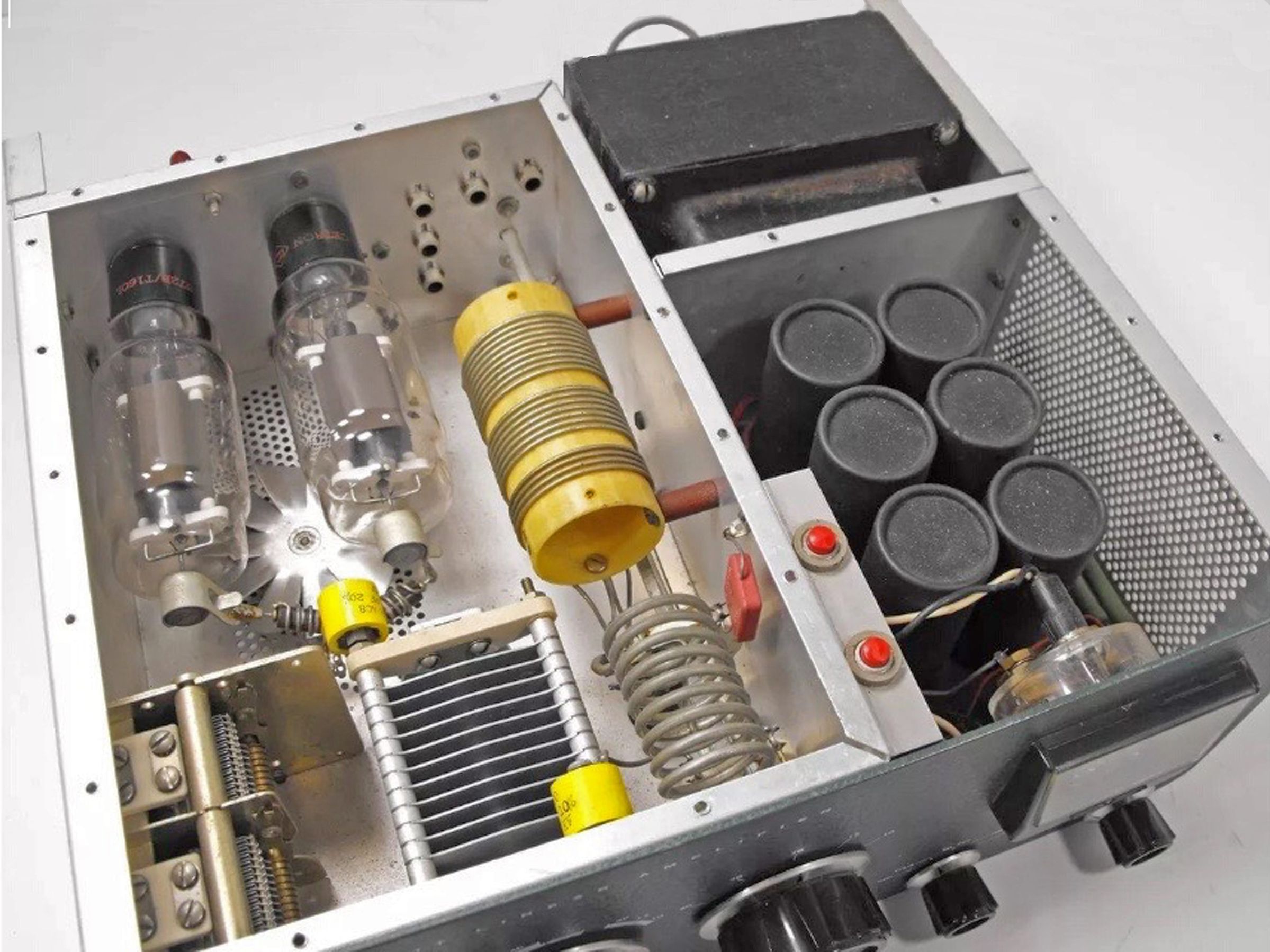
The SB-200(201) is rated at 1200 watts input PEP and 1000 watts CW using a pair of instant-on, fan-cooled, 572B (T160L) tubes running in parallel. It operates in grounded grid class B and requires 100 watts (nominal) of drive.
The SB-200 has an input impedance of 50Ω. The amp features a built-in, solid-state power supply with a circuit breaker (mounted inside the cabinet under the top cover), full metering, an ALC connection, a built-in SWR bridge, and pre-tuned cathode input circuitry.
The only difference between the SB-200 and the SB-201 is frequency coverage. The 200 covers 80-10 meters. The 201 covers only 80-15 meters. This change was dictated by a change in the regulations governing the manufacture of linear amplifiers.
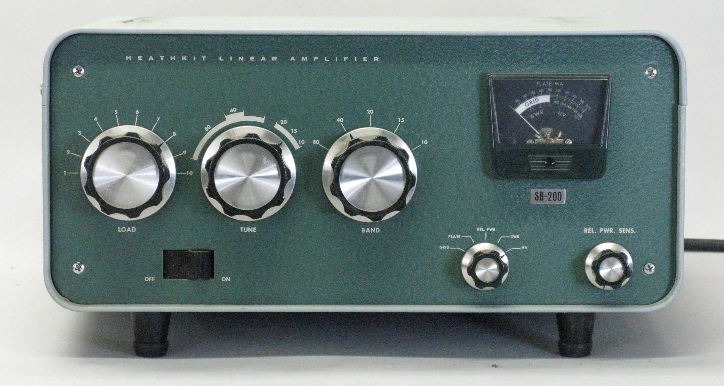
Front panel controls include a rocker-type on/off switch, tune, load, and band switch, relative power sensitivity, and meter function.
The illuminated meter will read grid, plate, relative power, SWR, and high voltage.
Rear panel connections include a ground post, RCA jacks for RF input, antenna relay, ALC, and an SO-239 RF output connector for a 50Ω antenna.
The SB-200 and 201 can be wired for either 120 VAC (16 amp max) or 240 VAC (8 amp max) operation. 240 VAC is recommended, but the amp will perform admirably on 120 VAC, assuming it is operating on a dedicated 20 amp circuit.
The SB-200 and 201 are styled to match the other SB-series gear and wear the classic two-tone green wrinkle finish paint.
The SB-200 remains as great a value today as when it was last sold in 1983. The SB-200 is in greater demand by virtue of its 10 meter coverage. The SB-200 is very common, with the SB-201 a bit less so. Watch for modifications.
Note: A modification of the transceiver is required use with the HW-12, HW-22, and HW-32. Refer to HW-12 for details.
Warning: Lethal voltages present when operating.
References:
Review, 73 Amateur Radio. Jan 1965, p. 78.
Review. QST. May 1965, p. 88.
Review. Jun-69 CQ, p. 62.
Meter lamp melts case. QST. Aug 1967, p. 40.
Use on 6 meters. QST. Jan 1969, p. 44.
Use on 6 meters. Ham Radio. Nov 1971, p. 38.
Use on 160 meters. Ham Radio. Aug 1975 p. 8
Use on 160 meters. QST. Sep 1979, p. 17.
Use on 160 meters. CQ. Jun 1984, p. 51.
Use on 160 meters. QST. Nov 1987, p. 32.
Use with HW-16. CQ. Feb 1969, p. 84.
Grid current problems. CQ. Dec 1969, p. 76.
Adjustable ALC threshold. CQ. Dec 1970, p. 75.
Use with 32S-3. CQ. Dec 1970, p. 75.
Modification for 8873 final. Ham Radio. Jan 1971, p. 32.
Intermittent output. CQ. Nov 1973, p. 10.
Electronic bias switch. Ham Radio. Nov 1976, p. 27.
Instant break-in for. QST. Mar 1981, p. 52.
Maintenance tips. QST. Jan 1986, p. 46.
Balanced grid circuit for. QST. Aug 1986, p. 38.
Balanced grid circuit for (more on). QST. Dec 1986, p. 45.
Power supply modifications. CQ. May 1987, p. 48.
“No holes” STBY switch mod. QST. Sep 1988, p. 45.
Panel labeling idea. QST. Dec 1988, p. 44.
Use with solid state XCVRs. QST May 1989, p. 48.
Use with solid state XCVRs. QST. Jan 1991, p. 37.
Tuning input circuit. Electric Radio. Apr 2007.
Review (SB-201). CQ. Feb 1983, p. 36.
Improving the high voltage diode stack. 73 Amateur Radio. Mar 1988, p. 20.
Harbach retrofits. QST. Jun 1995, p. 80.
Harbach retrofits. QST. Jul 1995, p. 29.
General information about SB series. Electric Radio. Sep 2016.
Band coverage:
SB-200: 80, 40, 20, 15 and 10 meters
SB-201: 80, 40, 20 and 15 meters
Drive power required: 100 watts
Maximum power input:
SSB: 1200 watts PEP
CW: 1000 watts
Duty cycle:
SSB: continuous
CW: 50% (key down time not to exceed 5 minutes)
Third order distortion: –30 db or better at 1000 watts
Output impedance: 50 to 75Ω unbalanced; variable pi-output; SWR not to exceed 2:1
Input impedance: 52Ω unbalanced; broadband pretend input circuit requires no tuning
Meter functions:
0-100 mA grid current (white area)
0-1000 mA plate current
0-1000 relative power
1:1 to 3:1 SWR
1500-3000 volts high voltage
Power requirements:
120 VAC, 16 amps maximum
240 VAC, 8 amps maximum
Tubes: (2) 572B / T-160L
Photos, general information and specifications from "Heathkit: A Guide to the Amateur Radio Products," by Chuck Penson, WA7ZZE. Used with permission.