Note
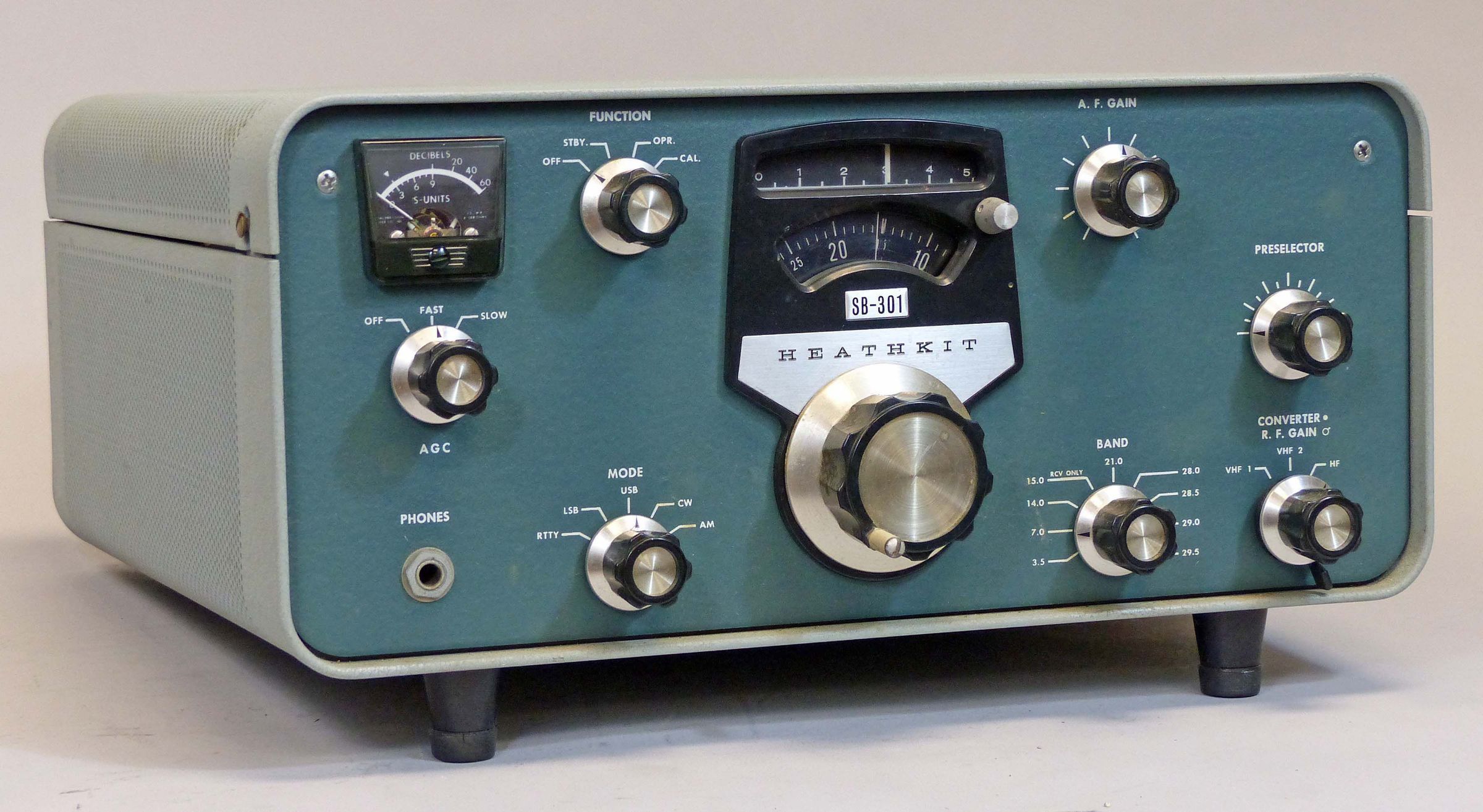
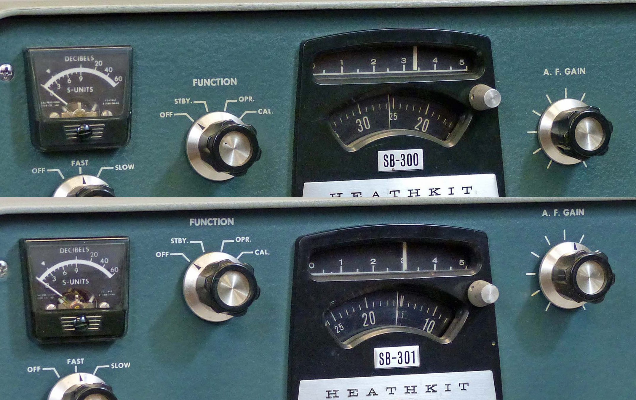
At first glance, the SB-301 appears to be the same as the SB-300. But the 301 represents a substantial refinement.
In addition to a meaningful improvement in sensitivity (managed mostly by a change in the tube lineup), improvements found in the 301 include the addition of a radio teletype (RTTY) position on the mode switch. When activated, a carrier at 3392.11 kHz is produced that causes detected signals at 2125 Hz and 2975 Hz (850 Hz shift) to fall within the SSB filter’s bandpass. 170 Hz RTTY can be tuned via the 400 Hz CW filter (if installed).
Another handy improvement is the addition of a 15 to 15.5 MHz range on the band switch, permitting the reception of WWV. An ANL circuit has been added to the 301 as well. It is activated by pulling out the audio gain control knob. The ANL operates within the IF stage rather than the audio stage and uses a full wave shunt across the second IF amplifier. It is self-biased and self-adjusts to the level of the incoming signal. Another small change—the SB-301 is capable of 240 volt operation.
Activation of the optional VHF converters has been simplified on the 301 by the addition of a front panel control. (On the 300 it was necessary to reach inside the receiver to switch the converters.) This control switches between the HF antenna input and the two converters and is mounted concentrically on the RF gain control.
The VHF converters are mounted externally on the rear panel of the receiver. Mounting holes are provided.
Note: The outputs of the optional VHF converters are connected to two rear panel RCA jacks, VHF #1 and VHF #2. These jacks are really just additional antenna inputs, so that without the converters, these same jacks could be used to select two additional antennas. For example, a Yagi could be connected to the main antenna jack, while a dipole and vertical could be connected to the VHF jacks.
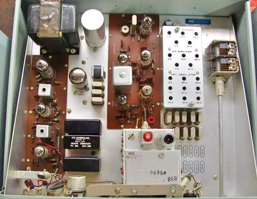
The crystal filters are different than those used in the SB-300. They are physically smaller and have slightly different characteristics. The optional AM and CW filters have been changed a little. The CW filter used to be 2.5 kHz at the –60 db point. It has been narrowed to 2 kHz. The AM filter, previously 3.5 kHz wide, is now 3.75 kHz wide at the –6 db points. Note: because of the different size and mounting hole configurations, SB-300 and 301 filters are mutually incompatible.
The rear panel is same as the SB-300, but two additional spare jacks have been added (on the right side). In 1970 the SB-301 was replaced by the solid state SB-303. Finished in classic SB two-tone green wrinkle.
Refer to SB-300 for additional discussion and interconnection requirements. Refer SB-100 for a discussion of crystal filter options.
References:
Review. QST. Mar 1967, p. 43.
Review. 73 Amateur Radio. Jun 1967, p. 76.
Improved switching from transmit to transceive. QST. Dec 1966, p. 21.
Spurious emission, relay problem, low drive. QST. Jan 1969, p. 16.
Operation outside the ham bands. CQ. Jan 1969, p. 96.
Improved AM. CQ. Jun 1969, p. 79.
Noise blanker info (brief). CQ. Aug 1969, p. 95.
Improved sidetone. Ham Radio. Oct 1969, p. 73.
Instant frequency change. QST. Jan 1970, p. 28.
Dual frequency operation. QST. Sep 1970, p. 50.
Apparent sensitivity. CQ. Mar 1971, p. 108.
Narrow shift RTTY reception. Ham Radio. Oct 1971, p 64.
Narrow shift RTTY reception. Ham Radio. Jun 1973, p 54.
Increase friction in worn zero set. QST. Jan 1973, p. 52.
Sidetone for. QST. Jul 1979, p. 49.
A 160 meter converter. Electric Radio. Jun 2001.
AM noise limiter mod. Electric Radio. Mar 2007.
General information about SB series. Electric Radio. Sep 2016.
Frequency range (MHz): 3.5–4.0, 7.0–7.5, 14.0–14.4, 15.0–15.5, 21.0–21.5, 28.0–28.5, 28.5–29.0, 29.0–29.5, 29.5–30.0
IF: 3395 kHz
Stability: < 100 Hz per hour after 20 minutes warmup; < 100 Hz for ±10% line voltage variation.
Visual dial accuracy: within 200 Hz on all bands
Electrical dial accuracy: within 400 Hz on all bands after calibration to nearest 100 kHz point
Backlash: < 50 Hz
Sensitivity: < 0.25 µV for 10 db signal plus noise-to-noise ratio for SSB
Overall gain: < 1.5 µV for 0.5 watts audio output
Modes: LSB, USB, CW, AM, RTTY
Selectivity:
SSB: 2.1 kHz at 6 db down, 5.0 kHz maximum at 60 db down
AM: 3.75 kHz at 6 db down, 10 kHz maximum at 60 db down
CW: 400 Hz at 6 db down, 2.0 kHz maximum at 60 db down
RTTY: 2.1 kHz at 6 db down, 5.0 kHz maximum at 60 db down
Image rejection: 60 db or better
IF rejection: 50 db or better
Spurious response: all below equivalent antenna input of 1µV
Audio response:
SSB: 350–2450 Hz nominal at 6 db
AM: 200–3500 Hz nominal at 6 db (with optional filter)
CW: 800–1200 Hz nominal at 6 db (with optional filter)
RTTY (normal): 1840–3940 Hz nominal at 6 db
RTTY (narrow shift): 2690–3090 Hz nominal at 6 db
Audio output: unbalanced nominal 8Ω and high impedance headphone
Audio output power: 1 watt with less than 8% distortion
Antenna input impedance: 50Ω nominal
Muting: open external ground at mute socket
Crystal calibrator: 100 kHz
Power requirements: 120/240 VAC, 50/60 Hz, 50 watts
Tubes: (1) 6BZ6, (3) 6AU6, (1) 6AB4, (1) 6AS11, (2) 6BA6, (1) 6HF8, (1) 6CB6
Photos, general information and specifications from "Heathkit: A Guide to the Amateur Radio Products," by Chuck Penson, WA7ZZE. Used with permission.