Note
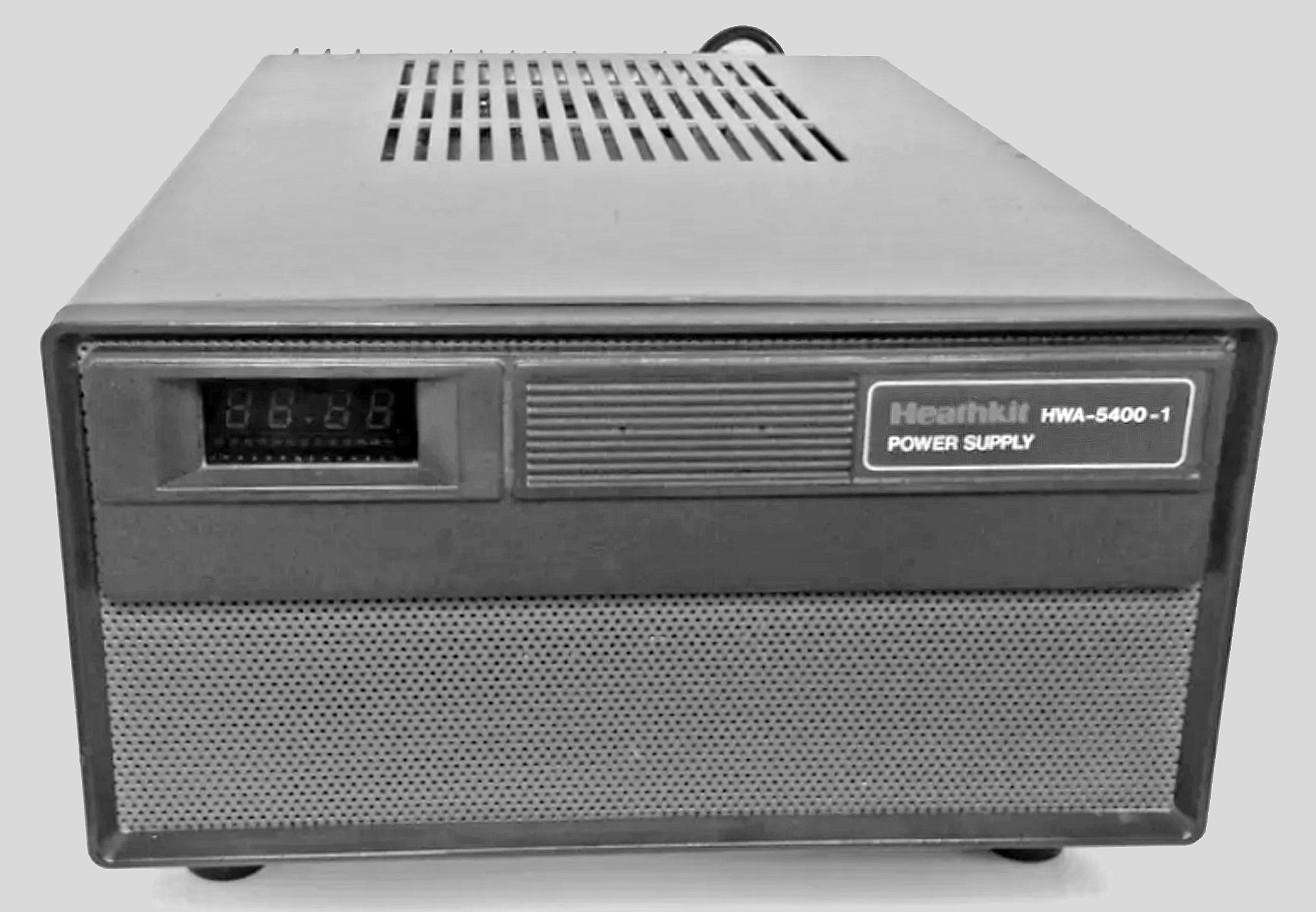
The HWA-5400-1 was designed specifically for the HW-5400 transceiver, and contains a power supply, a speaker and a clock.
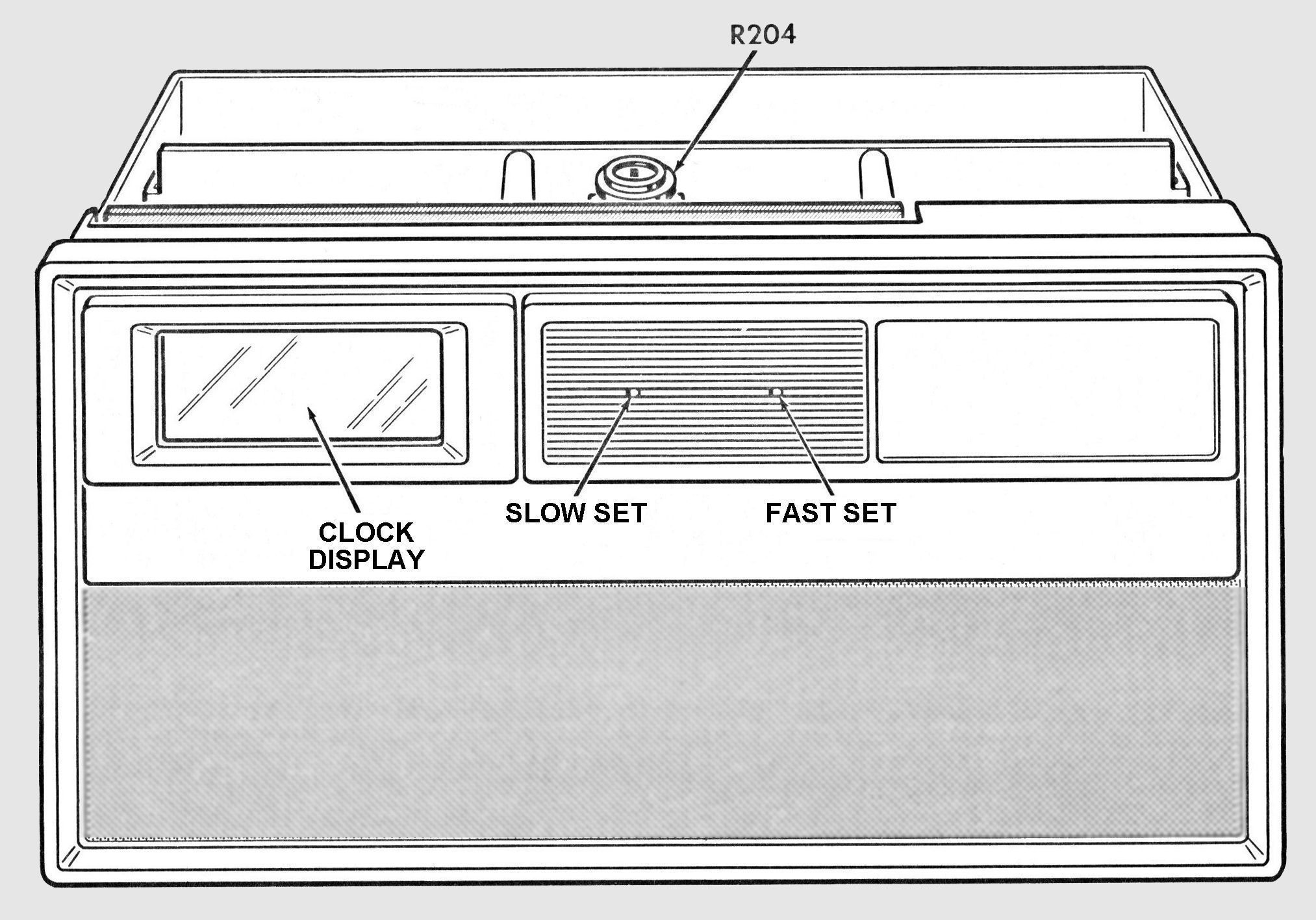
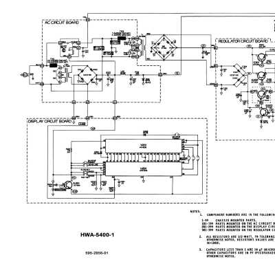
A four-digit vacuum fluorescent display reads time in 12 or 24 hour format, depending on the wiring option chosen during construction. There is also a wiring option for 50 or 60 Hz. R204, mounted at the top of the display circuit board, adjusts the brightness of the display.
A six-pin rear panel connector provides 5 VDC for the transceiver memory function, as well as a 13.8 VDC sense line used for voltage regulation. This same connector is used to route audio from the transceiver to the internal speaker.
The clock is set by depressing the FAST and SLOW setting buttons, located behind a front panel grill. A paper clip, toothpick or other slender tool is required for this procedure. After initial power up, the clock should be cycled through a complete 12 or 24 hour period before setting to the current time.
Line voltage: 120/240 VAC, 50/60 Hz
Output voltage: 13.8 VDC at rated load
Protection: 20-ampere DC output fuse. 7 and 4-ampere slow-blow fuses for 120 and 240 VAC primaries, respectively
Output current: As required by Transceiver, up to 18 (20 peak) amperes during transmit
DC output regulation: 7% from receiver load to transmitter load at 120 VAC primary. 4% additional with AC primary at 110-130 or 220-240 VAC
Ripple: 50 mV or less at rated load
Duty cycle: 9 amperes DC continuous. 18 amperes at 50% (5 min. on, 5 min. off)
Speaker: 4 ohms impedance, 300-3000 Hz response, 2 watts peak power
Clock: 4-digit blue fluorescent display in 12 or 24 hour format, synchronized to the line frequency.
Photos, general information and specifications from "Heathkit: A Guide to the Amateur Radio Products," by Chuck Penson, WA7ZZE. Used with permission.