Note
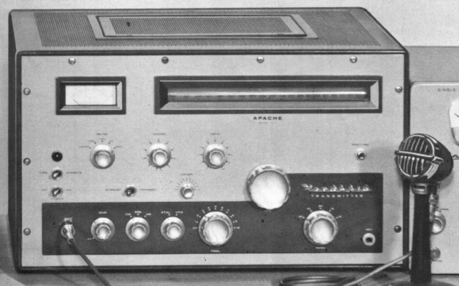
The TX-1 and its companion, the RX-1, were released as a pair in 1958 and were the first Heath amateur products to wear the now famous two-tone green paint. With a bench weight of 95 pounds, the TX-1 was typical of transmitters of the day.
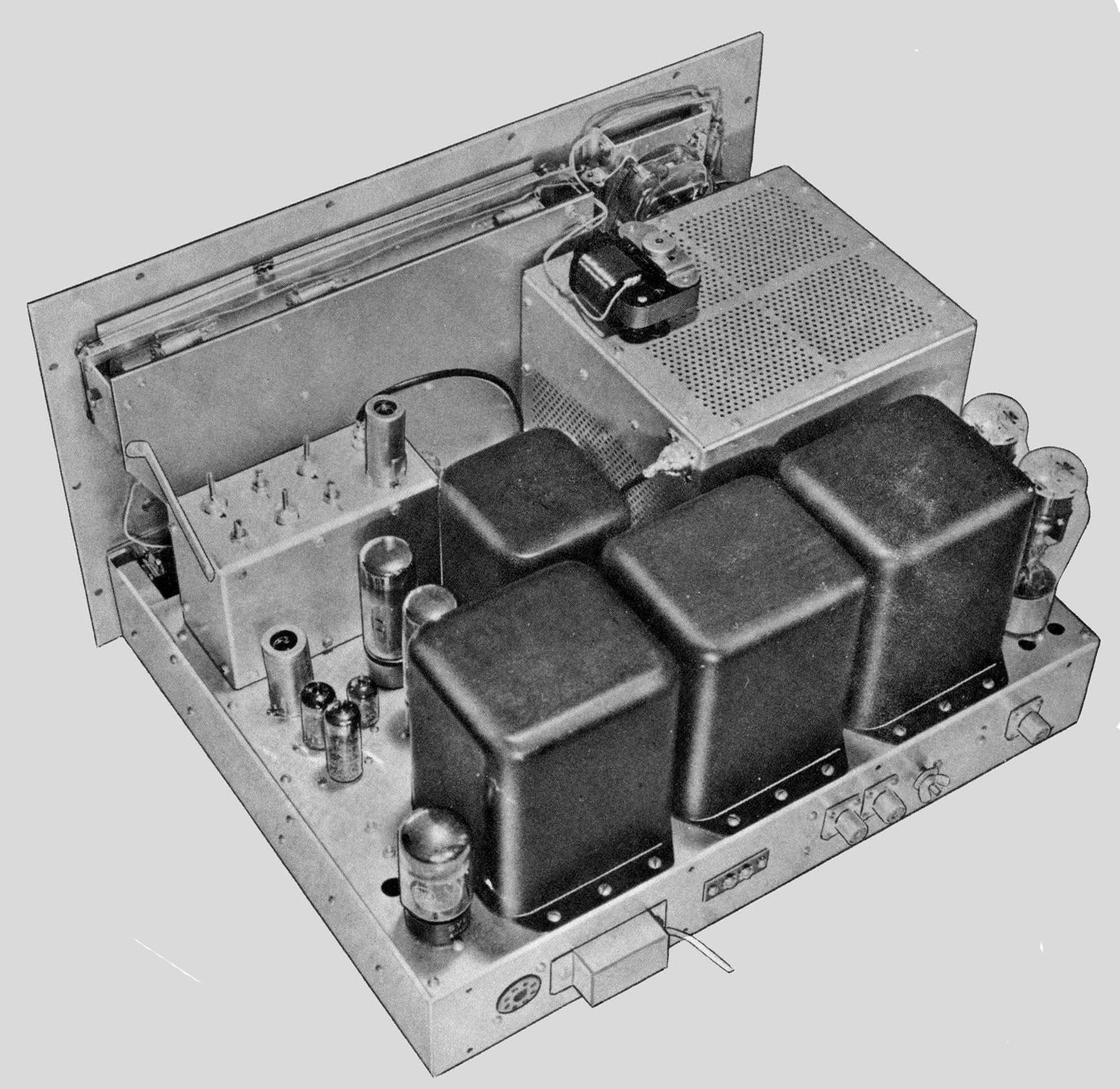
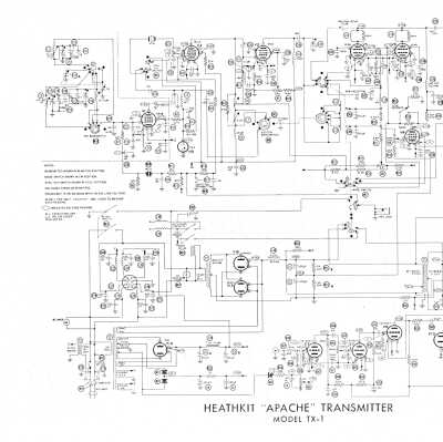
More than just a DX-100 in a new box, the TX-1 was a substantial improvement over the 100 and was marketed as a step up. The TX-1 is designed around 19 tubes including a pair of 6146 finals. Some of the biggest improvements were in the VFO, a Clapp oscillator (a series tuned Colpitts) in which the 6AU6 filament was left on all the time. The tube was mounted outside the VFO housing, and liberal use was made of temperature compensation components including heavily doped ceramic slug-tuned coils.
The Apache covers from 80-10 meters, and 11 meters with crystal operation. The TX-1 does not provide for operation on 160 meters, which is curious since the matching receiver (the RX-1) does.
The TX-1 has a rated input power of 150 watts AM and 180 watts CW, and its Pi-network output circuit will match from 50-72Ω. The unit features a built-in power supply (with a solid state bias supply), adjustable low-level speech clipping, “time sequence” keying for “chirpless break-in” CW, heavy shielding, provisions for one crystal frequency, and fan cooled finals. There is also a front panel selector switch to route the signal to a rear panel connector for use with the SB-10 SSB adapter unit (see entry). Note: information regarding operation with the SB-10 is not covered in the TX-1 assembly manual, but is provided instead in the SB-10 manual.
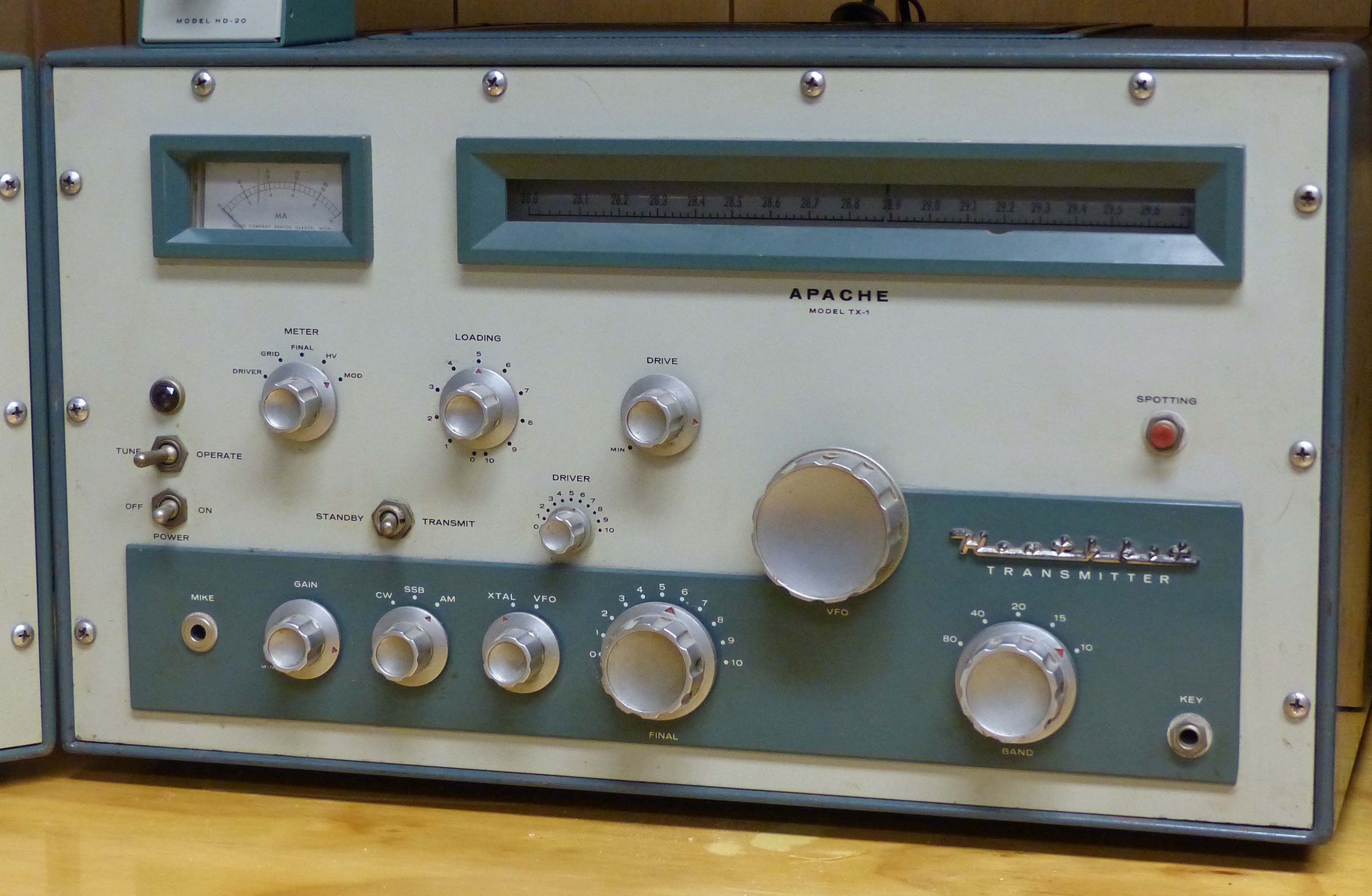
An illuminated panel meter reads drive plate current, final grid current, final plate current, final plate voltage, and modulator plate current. There are a full range of front panel controls. These include the band switch, VFO main tuning, final amp tuning, driver tuning, frequency control (VFO or crystal), mode, plate high voltage on/off, audio gain, main power, tune/operate, meter function, antenna loading, final amp drive level, and a spotting switch. The main modulation level control is adjusted with a screwdriver by reaching in through the key jack. In addition to the various controls, there is also a high voltage indicator light.
Refer to figure 1. On the rear panel is an octal accessory socket that provides an external duplication of the plate switch and 120 VAC for use with an antenna relay and/or receiver muting when the plate switch is on. This socket is plug-compatible with the VX-1. Also available on this socket is 350 VDC at 85 ma and 6.3 VAC at 3.5 amps. These voltages are primarily for use with the SB-10 SSB adapter.
A pair of screw terminal contacts near the center of the rear panel are provided for receiver muting and are wired as normally closed, and switch to open when the plate switch is on. They are easily rewired for normally open by changing the wiring on the relay. There are also two closely spaced SO-239 connectors on the rear panel. These are for use with the SB-10 SSB adapter. As viewed from the rear, the left connector provides RF to the SB-10. The right connector provides input to the final amp.
Since the RX-1 receiver had been designed and prototyped before the TX-1, and since the two units had to match, some tricky engineering was needed to fit the TX-1 into the the RX-1’s box. Among other things, this required some complicated mechanical linkages that ended up working pretty well—even if they did look a little strange.
The nick name “scratchy Apache” (not really heard much until recent years) refers to the TX-1’s audio quality and is probably undeserved. The TX-1’s audio response is about 300 to 3000 Hz and is really very clean. Any “scratchiness” heard may be the result of component failure or drift due to age, or to operator error.
As in the RX-1, the plastic dial drum is fragile and can crack with rough handling.
Two-tone green finish with darker green cabinet. Early units were shipped with satin finish metal knobs while later versions used polished knobs. The RX-1/TX-1 pair were the last big/heavy radios Heath made and were replaced by the SB-300/400 series.
References
Review. Radio News, Mar 1959, p. 62.
Review. QST. Mar 1959, p. 44.
Review. CQ. Aug 1959, p. 55.
Correcting grid current. QST. Jun 1959, p. 62.
Spotting switch modification. QST. Dec 1959, p. 52.
Adjustments made easy. QST. Mar 1960, p. 48.
Final grid current problems. CQ. Mar 1961, p. 66.
Tips. CQ. Mar-61, p. 66.
TVI precautions. CQ. Jul 1961, p. 76.
Modification. QST. Nov 1960, p. 54.
Adding break-in. 73 Amateur Radio. Jan 1962, p. 40.
Chirp fix. CQ. May 1962, p. 76.
Capacitor problems. CQ. Jun 1962, p. 35.
Use with HA-10 / SB-10 / phone patch. CQ. Jul 1962, p. 80.
Improvements. CQ. Dec 1962, p. 66.
VFO drift. CQ. Oct 1964, p. 79.
Drive problems with SB-10. CQ. Nov 1964, p. 114.
Conversion (very brief). CQ. Aug 1966, p. 90.
Use on 1815 kHz (brief). CQ. Jan 1968, p. 78.
Use on 6 meters. CQ. Oct 1969, p. 73.
Chirp problems. CQ. Jul 1970, p. 84.
Excessive drift (brief). CQ. Jun 1972, p. 12.
Marriage of a DX-100, TX-1 and FT-101. Electric Radio. Jan 2009.
RF power input: 150 watts AM, 180 watts CW
Output impedance: 50 to 75Ω
Output coupling: Pi network, coaxial
Operation: crystal or VFO; CW or AM; using time-seqeuence keying, SSB operation requires the SB-10 adapter
Band coverage: 80, 40, 20, 15 and 10 meters (11 meters with crystal control)
Audio output: 100 watts at 300 to 3000 Hz, with adjustable low-level speech clipping; 500Ω output available
Power requirements:
120 VAC, 50/60 Hz
standby (AM/CW): 150 watts
standby (with SB-10): 230 watts
CW: 420 watts (intermittent)
AM: 500 watts (peak)
SSB (with SB-10): 500 watts (peak)
Size: 19.5 wide x 11.75 high x 16 deep; Weight: 95 lbs
Tubes: (1) 0A2, (2) 0B2, (1) 5V4, (1) 5R4, (1) 6AU6A, (1) 6AL5, (1) 6AQ5, (1) 6CL6, (2) 6CA7/EL34, (1) 12AU7, (1) 12AX7, (1) 12BY7, (1) 5763, (2) 6146
Photos, general information and specifications from "Heathkit: A Guide to the Amateur Radio Products," by Chuck Penson, WA7ZZE. Used with permission.