Note
QST, Nov 1971, p. 121.
QST, Jan 1972, p. 121.
QST, Jan 1973, p. 113.
QST, Apr 1973, p. 137.
QST, Jan 1974, p. 150.
QST, Feb 1975, p. 165.
First referred to as the model 505, QST Oct 1972, p. 2.
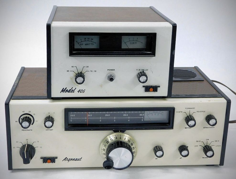
The Ten-Tec Argonaut 505, introduced in 1971, was the first in a long line of Ten-Tec transceivers, and marked a turning point in the evolution of QRP amateur radio equipment. At the time, most transceivers were large, tube-based, and ran high power. Ten-Tec—then a young Tennessee-based company—set out to prove that serious amateur operation could be done with solid-state, low-power gear. The 505 was among the first commercially successful QRP transceivers, preceding the later and better-known Argonaut 509.
The Argonaut 505 covered the major HF bands—80 through 10 meters—and offered both SSB and CW modes in a compact, lightweight cabinet. Its solid-state design made it rugged and reliable, ideal for portable or field operation since it can be operated on batteries. The rig’s roughly 3- to 5-watt output was modest, but its clean signal, good frequency stability, and true QSK CW capability gave it surprising performance for its size.
Ten-Tec designed the 505 entirely in-house, emphasizing user serviceability with plug-in circuit boards and modular construction—an unusual feature at the time. It became a cornerstone for Ten-Tec’s philosophy of “American-made, operator-focused” design.
While later models added refinements, the Argonaut 505 remains beloved as the radio that introduced thousands of operators to the joy and challenge of QRP—doing more with less, and proving that good operating skills often outweigh transmitter power.
Replaced by the Argonaut 509 in 1975.
Specifications
General
Frequency Coverage: 3.5–4.0 MHz, 7.0–7.5 MHz, 14.0–14.5 MHz, 21.0–21.5 MHz, 28.0–30.0 MHz
Filtering: 9 MHz crystal filter, 2.5 kHz bandwidth, 1.7 shape factor @ 6/50 dB points.
Automatic sideband selection, reversible
Fully solid state
All circuits Permeability tuned
Seven plug-in circuit boards
Direct frequency readout.
Tuning rate: about 25 Hz per revolution
Vernier tuning. Dial accuracy +/- 5 kHz (slightly more at 10 meters)
Stability: Drift less than 100 Hz
Power required: 12-15 VDC @ 150 mA receive, 800 mA transmit at rated output.
Construction: Aluminum chassis, top and front panel, molded plastic end panels. Cream front panel, walnut vinyl top and end trim.
Receiver
Sensitivity: Less than 0.5 uV for 10 dB S+N/N
Backlash: < 50 Hz
"S" Meter
AGC fast attack, slow decay
CW sidetone and RIT
Separate AF and RF gain controls
Tuned MOSFET RF amplifier and mixer
Frequency response: 300–3000 Hz
Audio distortion < 2%, internal speaker
Dial accuracy: ± 5 KHz (slightly more above 28 MHz)
Dial drift: < 100 Hz
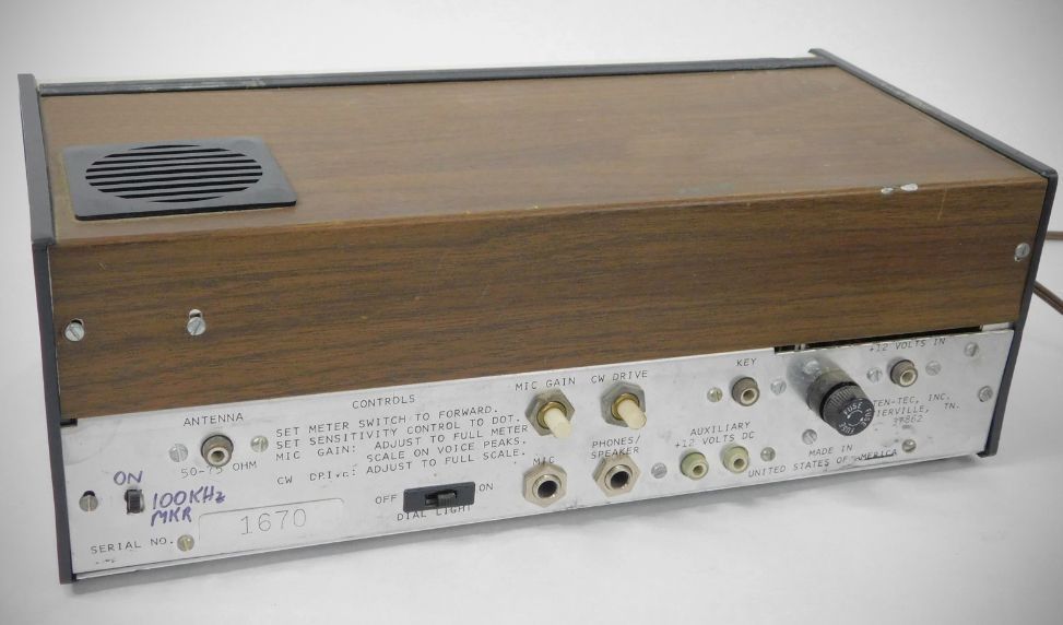
Headphone/external speaker jack
Transmitter
Input power:
5 watts PEP
5 watts CQ
Output circuit: broadband 50–75Ω impednace
Broad band final amplifier eliminates tuning
50 - 75 ohms output impedance
Drift: less that 100 Hz
PTT
Full CW break-in
SWR bridge
Integral TVI filter
CW sidetone
Integrated circuit balanced modulator
Automatic CW offset or approximately 700 Hz
Shaped keying
Accessories
Linear Amplifier Model 405
Power Supply Model 251
Power Supply Model 210
Microphone Model 215
Keyer Model 605 (KR-5)