Note
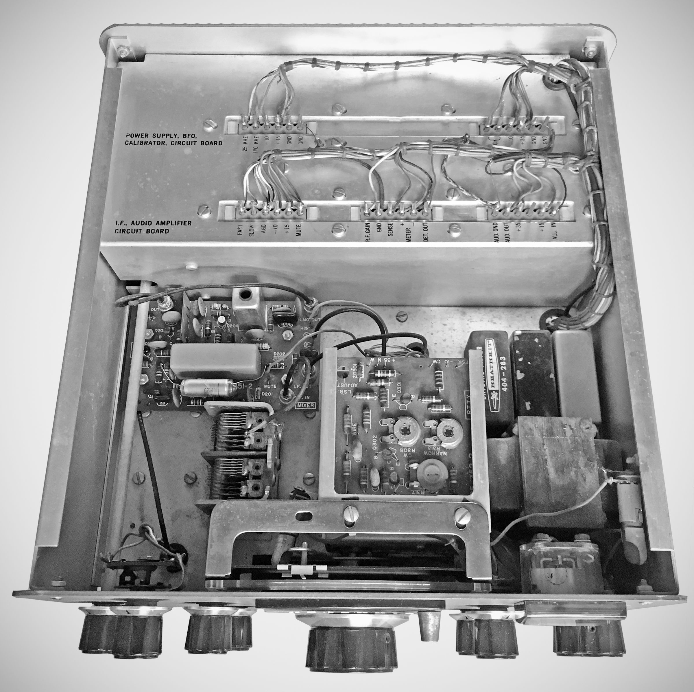
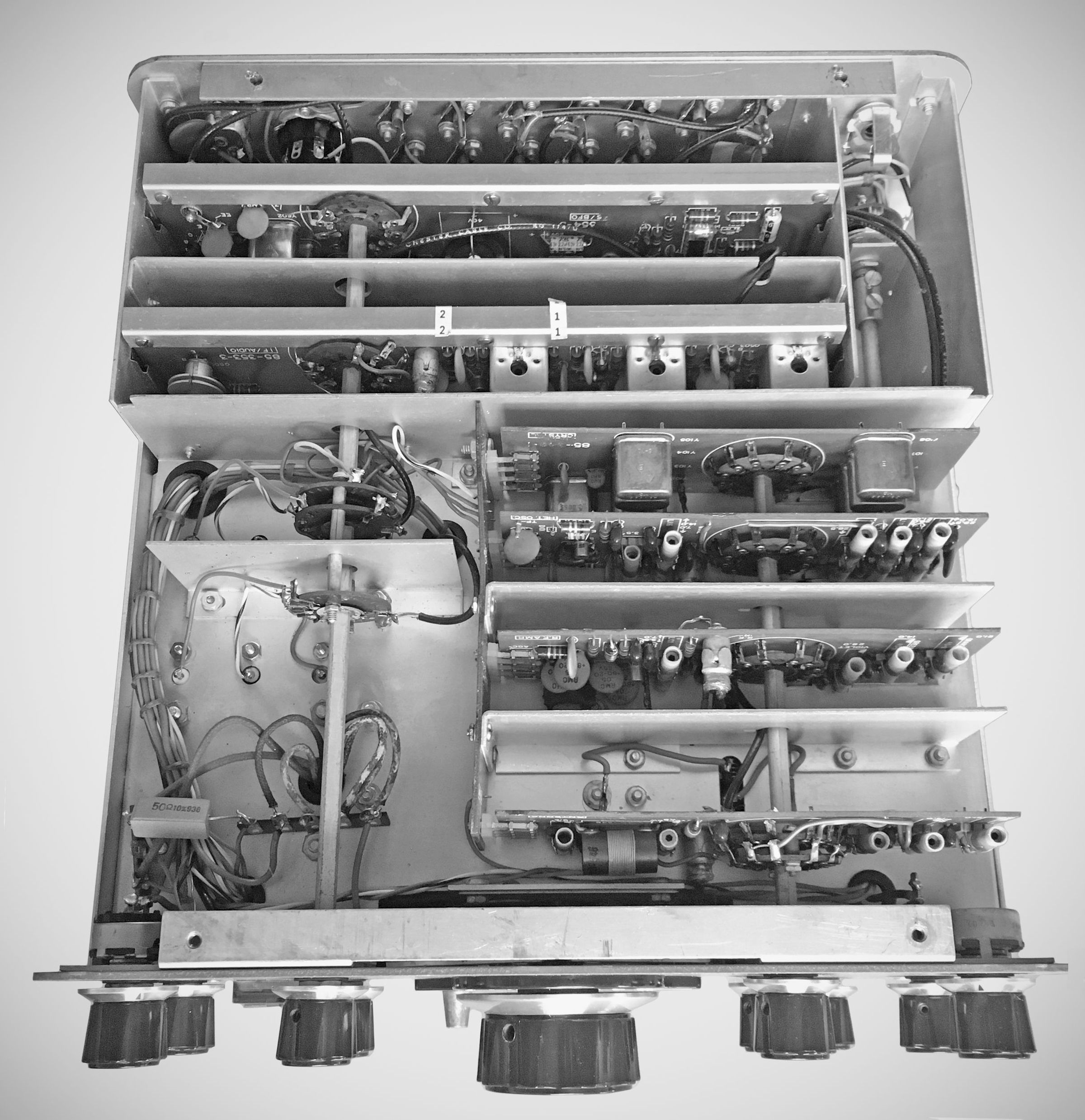
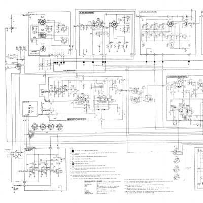
The SB-303 was the first fully solid-state member of the SB series and was extremely popular. Using 27 silicon transistors, one IC, a handful of diodes, and the same LMO and dial assembly found in the SB-102, the SB-303 is built on eight PC boards, six of which plug in to the main chassis.
Its basic features and specifications are very much like the SB-301. It also looks very much like the 301, but is 2.75 inches narrower.
The conversion scheme and IF frequencies are identical to the 300 and 301, and like the 301, the 303 covers 500 kHz portions of the 80 through 10 meter ham bands, as well as 15 to 15.5 MHz for WWV reception. The 10 meter band is covered in four 500 kHz segments.
The use of dual gate MOSFETs in the RF amplifier, mixer, and IF amplifier, made the SB-303 the most sensitive receiver it ever designed. Warm up stability was also cut to just ten minutes.
The SB-303 also features an improved crystal calibrator. In addition to 100 kHz markers, the new calibrator also provides switch selection of 25 kHz markers. And in addition to the standard RF gain control, Heath has added an RF attenuator control with a 40 db range.
As with the SB-301, the SB-303 can be used to transceive with the SB-400 and 401. And as with the 301, there are provisions for two VHF converters. Heath did not make VHF converters specifically for the SB-303. It is possible to use the SBA-300-3 and SBA-300-4 six- and two-meter converters with the SB-303, though a separate power source would be required. AGC for the converters is available from the 303’s octal socket. Refer to SBA-300-3 for additional discussion and requirements.
Note: The outputs of the optional VHF converters are connected to two rear panel RCA jacks, VHF #1 ANT and VHF # 2 ANT. These jacks are really just additional antenna inputs, so that without the converters, these same jacks could be used to select two additional antennas. For example, a Yagi could be connected to the main antenna jack, while a dipole and vertical could be connected to the VHF jacks.
The 303 comes standard with a 2.1 kHz SSB filter and has provisions for two optional filters—a 3.75 kHz AM filter and a 400 Hz CW filter. These are the same filters used SB-301, but different from those in the 300. The unit will not function in the AM or CW mode unless the appropriate filters have been installed, although reception of AM and CW is still possible in the SSB mode.
Interconnection cables should be 24 inch lengths of RG-62/U, except for the LMO cable, which should be a 24 inch length of RG-174/U.
The 303 does not have a cabinet with the hinged top to permit easy access to the inside—presumably because you would not be changing tubes. Therefore the only way to check for the presence of the filters is to either remove the unit from its case (by removing the rubber feet) or to try to look through the cabinet perforations. The filters are located just behind the power transformer, which is located just behind the S-meter. There is room for three filters and they are (from left to right as viewed from the front) SSB, CW, and AM. The CW and AM filters may or may not be labeled as such.
As mentioned earlier, the PC boards may be unplugged and removed or extended for service. To remove or extend the boards requires that the band switch control shaft and/or the mode switch control shaft be removed first. Both large and small PC board extender cards were originally supplied with the SB-303 but are rarely found with the unit today.
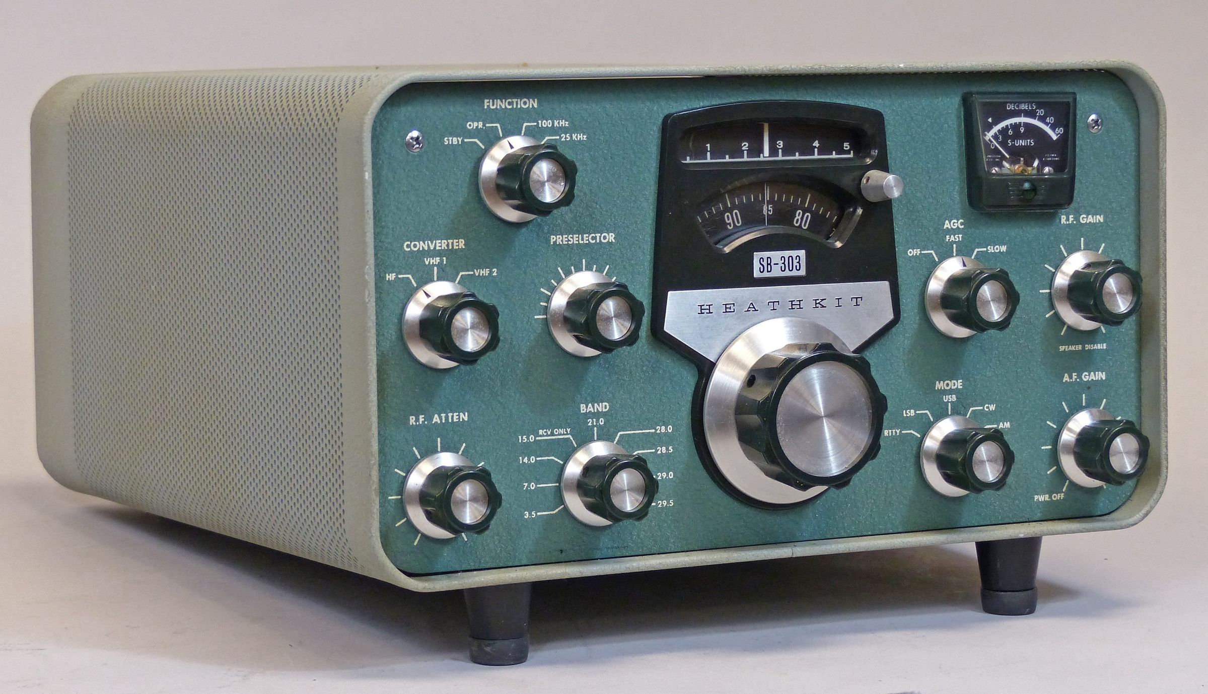
Front panel controls include function, converter (for selection of HF antenna or VHF converters), band, RF attenuator, main tuning, zero set, AGC (fast, slow, off), mode, AF gain/power on-off, and RF gain (pull to disable speaker). There is no ANL.
Internal controls include IF/Audio-bias adjust, meter zero, meter full scale, BFO power supply adjust, 100 kHz adjust, RTTY wide/narrow shift, CW shift, LSB adjust, and +15 VDC adjustment.
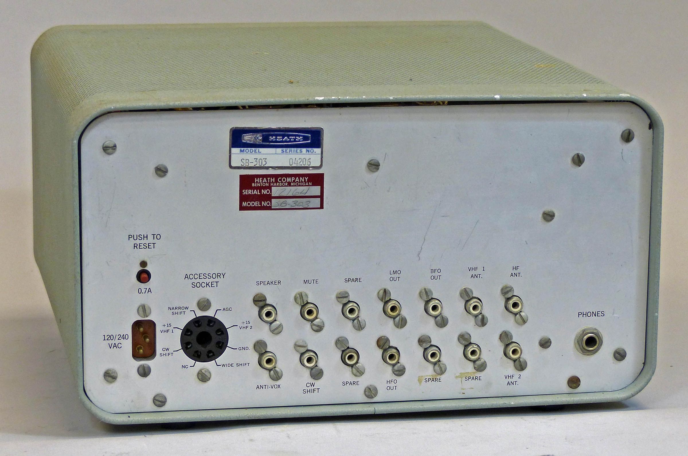
Rear panel connections include a quarter-inch headphone jack and RCA jacks for HF input, VHF #1 input, VHF #2 input, mute, anti-VOX, 8Ω speaker (there is no built-in speaker), HFO out, BFO out, LMO out, and CW shift (CW shift is duplicated on the octal socket. Refer to RTTY FUNCTIONS below). There are also four spare jacks as well as an octal accessory socket providing power for the optional VHF converters and input for a RTTY keyboard.
The 303’s built-in power supply can be wired for 120 or 240 VAC 50/60 Hz operation and is protected with a rear panel circuit breaker. The 303 is a nice receiver—even by today’s standards. Painted in classic SB two-tone green wrinkle.
LMO LOAD
To use the SB-303 when it is not connected to the SB-400 or 401, the LMO load must be attached for proper operation. The LMO load is a 47Ω resistor attached to an RCA plug, and inserted into the LMO jack on the rear panel.
RTTY FUNCTIONS
RTTY shift functions are provided from the accessory socket and are for use when transceiving with the SB-400/401, for example. The CW shift pin (also available from a rear panel RCA jack) provides for connection of a key for use in CW identification while operating RTTY. The wide and narrow shift pins are for connection to a RTTY keyboard. When transceiving, the SB-303 controls the frequency of the transmitter, and these functions effect the appropriate shift of the SB-303’s LMO, and consequently, the transmitted frequency.
References:
Review. CQ. Apr 1971, p. 43.
Review. QST. Jul 1971, p. 48.
Improved CW reception. QST. Jul 1972, p. 21.
Improved CW reception. QST. May 1973, p. 39.
Internal noise fix. CQ. Oct 1971, p. 79.
Increase friction in worn zero set. QST. Jan 1973, p. 52.
10 MHz coverage for. Ham Radio. Feb 1974, p. 61.
A Noise Blanker That Works. QST. Jan 1977, p. 39.
Variable-Bandwidth Tuning. QST. Sep 1977, p. 19.
Sidetone and AGC mods. QST. May 1979, p. 45.
Sidetone for. QST. Jul 1979, p. 49.
Noise blanker for. QST. Sep 1979, p. 45.
Zero-set dial modification. QST. Feb 1980, p. 44.
Reduction of internal noise. Ham Radio. Jun 1982, p. 70.
Frequency range (MHz): 3.5–4.0, 7.0–7.5, 14.0–14.4, 15.0–15.5, 21.0–21.5, 28.0–28.5, 28.5–29.0, 29.0–29.5, 29.5–30.0
IF: 3395 kHz
Frequency stability: less than 100 Hz drift after 10 minute warmup. Less that 100 Hz drift for ±10% change in line voltage
Frequency selection: built-in LMO
Modes: USB, LSB, CW, AM, RTTY
Sensitivity: less than 0.25 µV for 10 db signal-plus-noise to noise ratio for SSB
Overall gain: less than 1.5 µV input for 0.5 watts audio output
AGC characteristics:
blocking: greater than 3.0 V CW/SSB/RTTY
dynamic range: greater than 150 db CW/SSB
RF attenuator range: 40 db
Selectivity:
SSB: 2.1 kHz at 6 db down, 5.0 kHz maximum at 60 db down
AM: 3.75 kHz at 6 db down, 10 kHz maximum at 60 db down
CW: 400 Hz at 6 db down, 2.0 kHz maximum at 60 db down
RTTY: 2.1 kHz at 6 db down, 5.0 kHz maximum at 60 db down
Image rejection: 60 db or better
IF rejection:
3.395 MHz: greater than 55 db
8.595 MHz: greater than 50 db
Spurious response: all below 1.0 µV equivalent
Operating temperature range: 10 to 50 C
Visual dial accuracy: within 200 Hz on all bands
Electrical dial accuracy: within 400 Hz on all bands after calibration to nearest 100 kHz or 25 kHz point
Dial backlash: less than 50 Hz
Calibration: every 100 kHz or 25 kHz
Antenna impedance: 50Ω nominal, unbalanced
Audio response:
SSB: 350 to 2450 Hz nominal at 6 db
AM: 200 to 3500 Hz nominal at 6 db
CW: 800 to 1200 Hz nominal at 6 db
RTTY: 1840 to 3940 Hz nominal at 6 db
Audio output impedance:
speaker: 8Ω
headphones: low impedance
Audio output power: 4 watts at less than 10% distortion
Muting: open external ground at mute jack
Power requirements: 120/240 VAC, 50/60 Hz, 40 watts maximum
Photos, general information and specifications from "Heathkit: A Guide to the Amateur Radio Products," by Chuck Penson, WA7ZZE. Used with permission.