Note
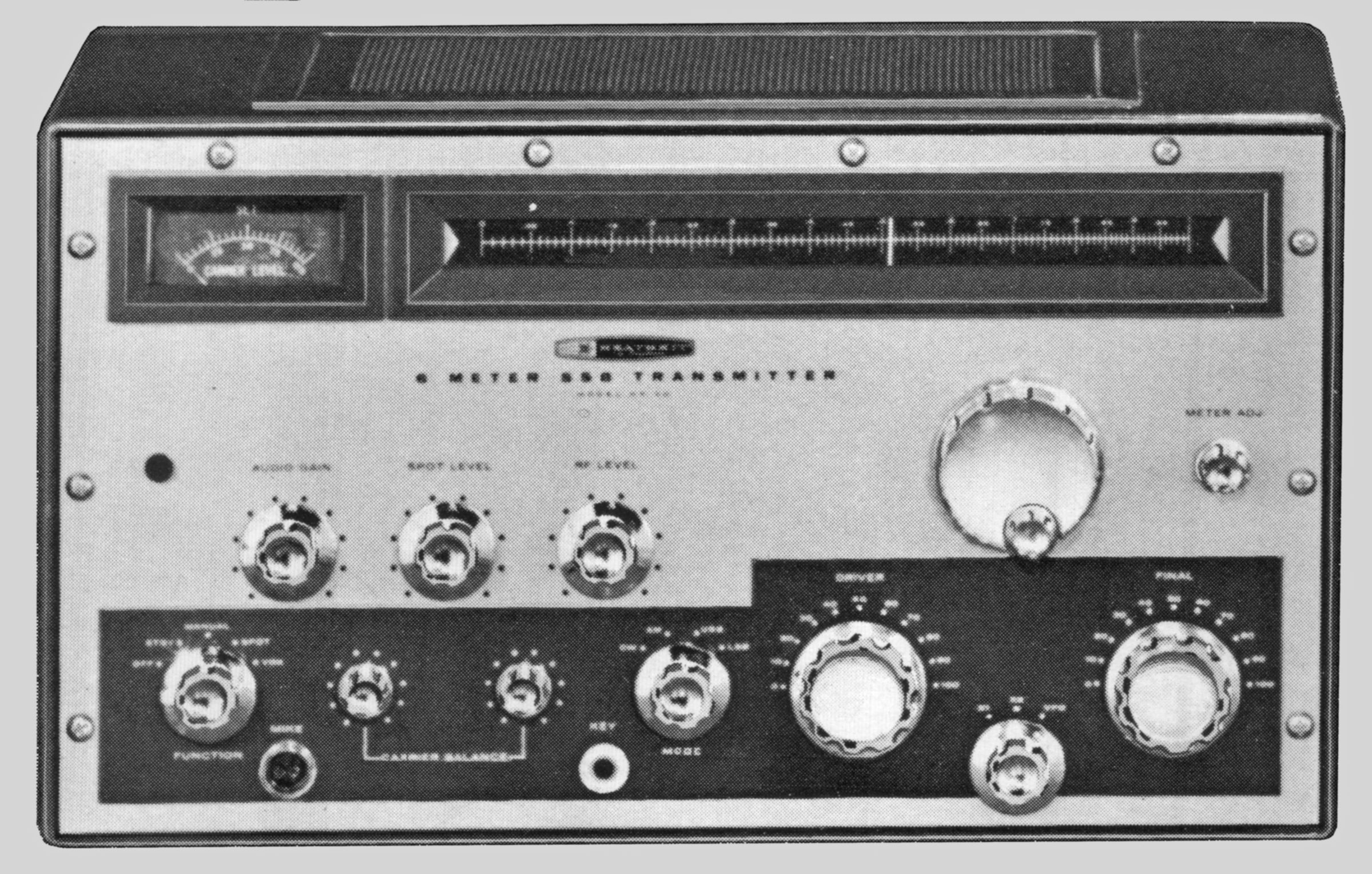
Looking much like a smaller version of the TX-1, the HX-30 was Heath’s first VHF sideband transmitter and was well received by VHF enthusiasts.
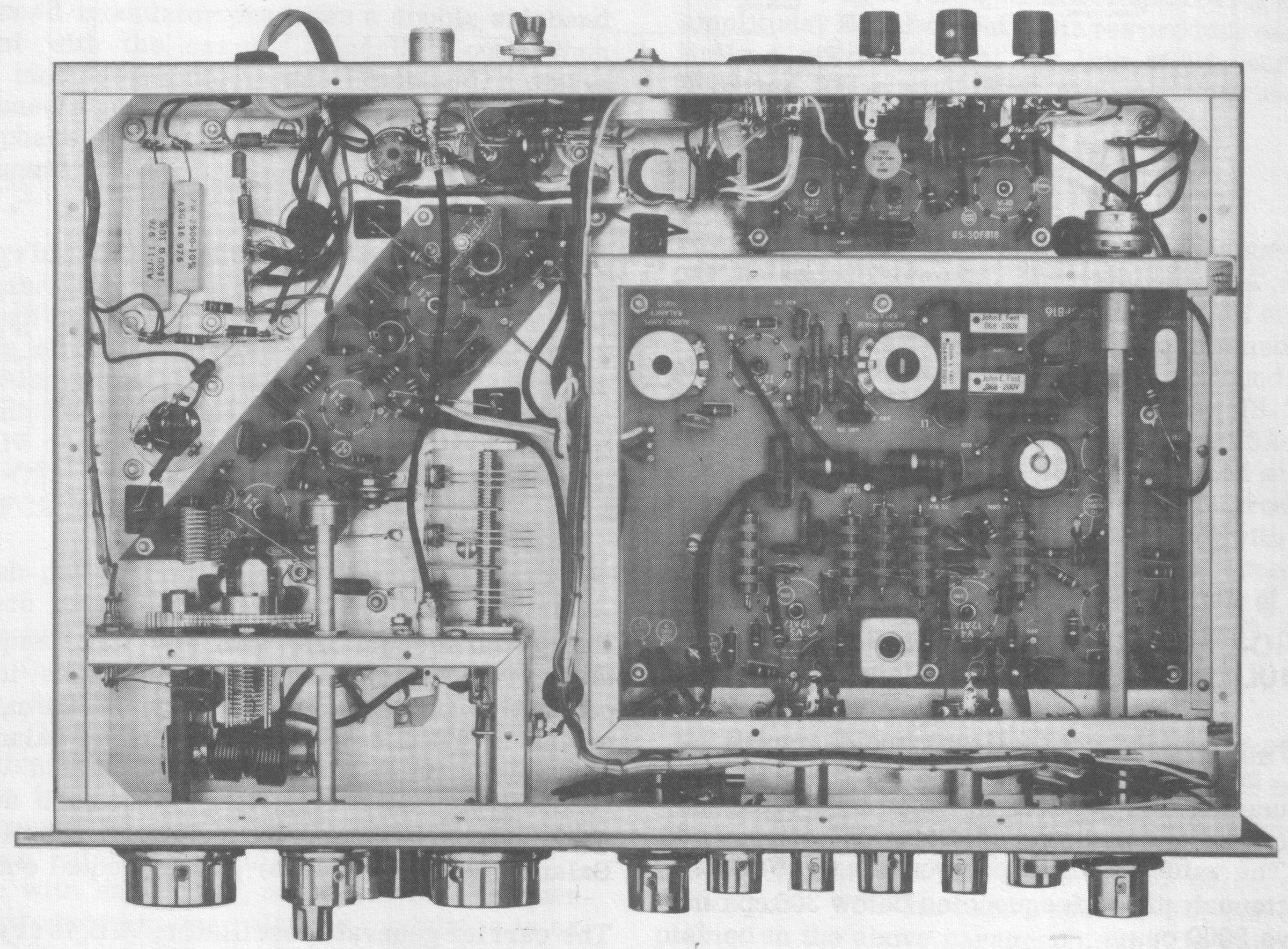
The HX-30 uses 14 tubes and operates CW, AM, USB, and LSB. The unit is an unusual design in that three of its four circuit boards are secured to the underside of the chassis, with tube sockets mounted on the foil side of the boards. Holes in the chassis provide access to the sockets.
The unit uses crystal-controlled carrier and heterodyne oscillators together with an audio phase-shift scheme to generate the output.
The HX-30 will cover any one 1 MHz portion of the six-meter band. The basic frequency generation method works in the following way. A carrier is produced at 11.5 MHz and is mixed with the heterodyne oscillator frequency of 30.5 MHz to produce a 42 MHz signal. This 42 MHz signal is mixed with the VFO output from 8 to 9 MHz to produce an output from 50 to 51 MHz.
Since there is no band switch, changing the heterodyne oscillator crystal is required to move to a different portion of the band. Changing the heterodyne oscillator crystal to 31.5 MHz (for example) would produce an output between 51 and 52 MHz. While somewhat inconvenient, this system—together with a very well made and temperature compensated VFO—provides excellent stability.
The HX-30 was originally supplied with one heterodyne oscillator crystal to provide output from 50 to 51 MHz. Additional crystals could provide coverage to 54 MHz. Note: Changing the heterodyne crystal requires major realignment of the transmitter. Refer to Pictorial A for the location of the crystal.
Running SSB, the transmitter will provide 8 to 10 watts PEP output. On AM or CW the output is only 3 to 4 watts. Carrier suppression is better than 50 dB, and unwanted sideband suppression is better than 40 dB.
Features include a built-in power supply, VOX or PTT control, switch selection of USB, LSB, AM, or CW (grid block keying), a built-in VFO, provision for two crystal frequencies, and selectable temperature compensation. The illuminated slide-rule dial drive uses Heath’s famous (or infamous) gear-and-pulley tuning assembly—the repair of which is a sobering experience.
Front panel controls include audio gain, spot level, RF level, function, carrier balance, mode, driver tune, final tune, frequency control, meter adjust, and main -tuning, while the output loading and coupling controls are placed inside the cabinet (at the right, front corner) and are accessible by opening the hatch on the top of the cabinet. Also on the front panel are the mic and key jacks and a red panel light that indicates “on air” status.
Controls for the adjustment of bias, VOX delay, sensitivity and anti-trip are located on the rear apron along with an SO-239 for a 50-75Ω antenna, a ground post, and an 11 pin accessory socket. Pins on this socket include four sets of contacts that open or close with transmit, a switched 117 VAC output for use with an antenna relay, and a chassis ground. Refer to Figure 1 for details.
Alignment of the HX-30 required a VTVM, a dummy load, a scope, a sine wave audio generator, and a frequency meter. All things considered, the HX-30 was a very well-designed transmitter and produces a clean, stable signal with great audio and solid CW.
The unit is enclosed in a copper-clad steel cabinet and wears Heath’s official two-tone green. The knobs are polished aluminum, as opposed to the brushed aluminum knobs used on the VHF-1. Also note that the main tuning knob is a “spinner knob.”
See also matching HA-20 amplifier. Curiously, Heath never made a matching receiver.
CRYSTAL FREQUENCY CALCULATIONS
Use FT-243 crystals between 7.9 and 9.0 MHz. Any given crystal will produce four different frequencies depending on the the frequency of the first heterodyne oscillator crystal.
For 50 to 51 MHz: operating frequency = crystal frequency + 42 MHz
For 51 to 52 MHz: operating frequency = crystal frequency + 43 MHz
For 52 to 53 MHz: operating frequency = crystal frequency + 44 MHz
For 53 to 54 MHz: operating frequency = crystal frequency + 45 MHz
References:
Review. 73 Amateur Radio. Apr 1963, p. 112.
Review. QST. May 1963, p. 51.
Frequency coverage: 50 to 54 MHz in four 1 MHz segments. One crystal supplied for coverage from 50 to 51 MHz.
Emission Types: USB, LSB, AM, CW
DC power input: 21 watts
RF output power:
SSB PEP: 8–10 watts
AM: 2–2.5 watts
CW: 8–10 watts
Carrier suppression: 50 db below maximum output
Unwanted sideband suppression: 40 db below maximum output at 1000 Hz
Distortion products: 30 db below maximum output at 1000 Hz
Hum and noise: 40 db below maximum output
Audio input: 0.007 volts minimum
Output impedance: 50 to 75Ω
Crystals:
Carrier generator: 11.5 MHz
First heterodyne oscillator:
50.0 to 51.0 MHz: 30.5 MHz (supplied)
51.0 to 52.0 MHz: 31.5 MHz (not supplied)
52.0 to 53.0 MHz: 32.5 MHz (not supplied)
53.0 to 54.0 MHz: 33.5 MHz (not supplied)
Second heterodyne oscillator:
VFO: 8.0 to 9.0 MHz
Crystal control: 7.8 to 9.0 MHz
Crystal type:
First heterodyne oscillator: HC-6/V (pin diameter: 0.050, spacing: 0.486)
Second heterodyne oscillator: FT-243
Audio frequency response: 300 to 3000 Hz
Keying: grid block with key click filter
Tuning ratio: approximately 45 kHz per revolution
Power requirements: 120 VAC, 50/60 Hz
standby: 77 watts
SSB: 95 watts
AM: 90 watts
CW: 95 watts
Tubes: (1) 0A2, (1) 6AK6, (1) 6AL5, (1) 6CB6, (1) 6CH8, (1) 6U8, (5) 12AT7, (2) 12AX7, (1) 6030
Photos, general information and specifications from "Heathkit: A Guide to the Amateur Radio Products," by Chuck Penson, WA7ZZE. Used with permission.