Note
The GR-43(A) is a Zenith Trans-Oceanic look-alike based loosely on the Royal 3000-1, and has many of the same features. It is not a replacement for Heath's own GC-1A “Mohican,” as the two radios were sold side-by-side from 1965 to 1968. The appeal of the GR-43 over the GC-1A is not entirely clear. While the GR-43 adds FM and longwave reception, the GC-1A provides full shortwave coverage, and is capable of AM, CW and SSB reception. Interestingly, they both weigh the same — 17 pounds. The difference in price is significant. The GR-43 was priced at $159 (when it overlapped with the GC-1A), while the GC-1A was only $90. So you are paying an additional $69 for longwave, FM and truncated shortwave with AM reception only. Nevertheless, it sold well enough to have a place in the catalog until 1972, a run of eight years.
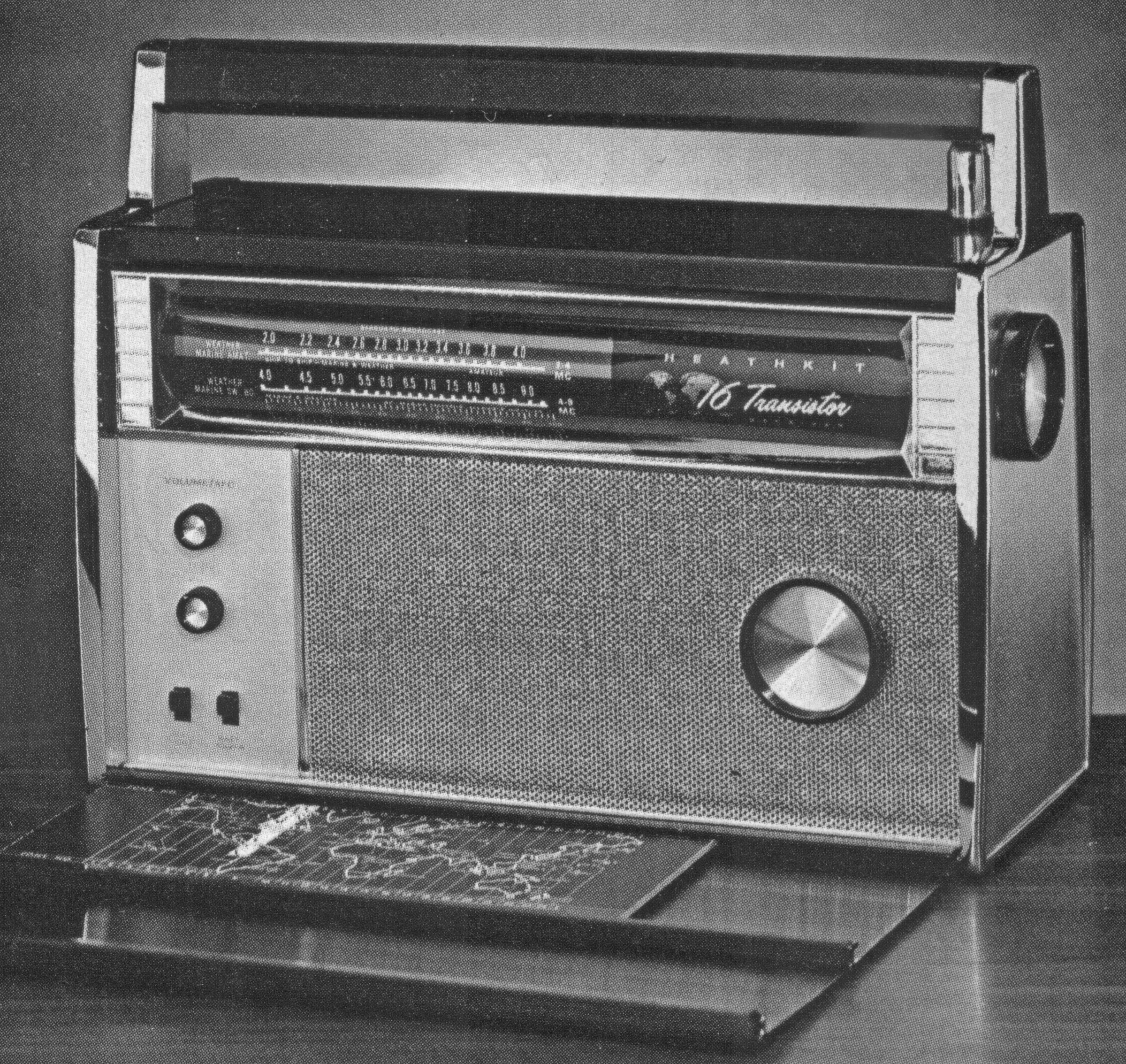
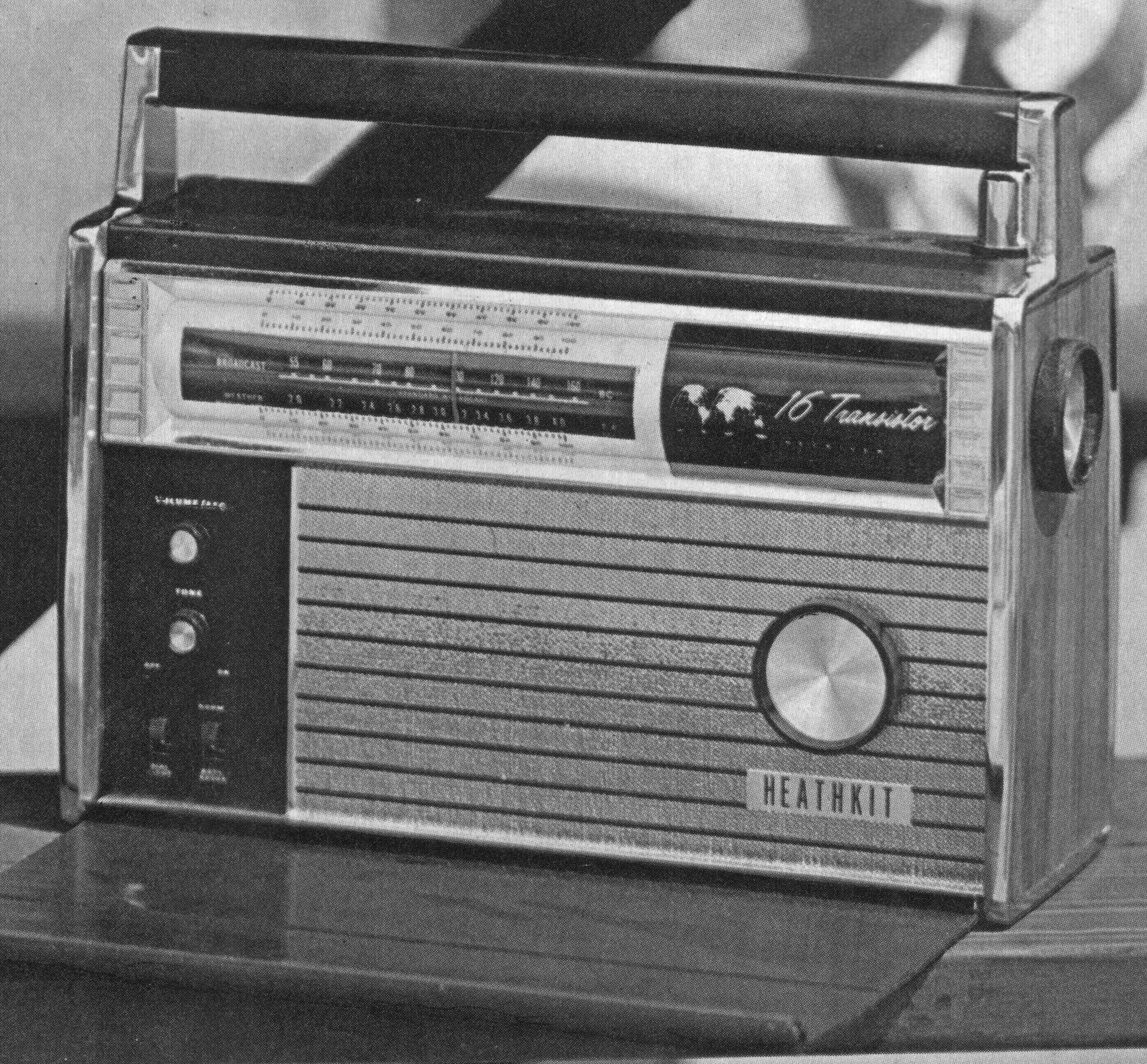
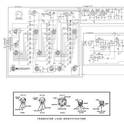
The radio uses 16 transistors and six diodes, and includes “44 pre-built and aligned RF circuits.” The separate AM and FM tuners are also pre-assembled and aligned. Heath said that the FM tuner and IF strip “are the same ones used in deluxe Heathkit FM stereo gear…” A rotating drum displays the chosen frequency band, which is selected with a knob on the right side.
Front panel controls including tuning, on-off/volume/AFC (push in to engage AFC), tone, and switches for the dial light and battery saver.
There are two antennas. A ferrite rod inside the handle is used for AM broadcast and longwave reception, and a five foot telescoping whip provides for FM and shortwave. Note that the ferrite rod antenna is directional, so that the entire radio may have to rotated for best reception. External antennas may be connected as discussed below.
The front and rear panels are hinged and are kept secured with magnetic catches. The front panel opens to reveal the tuning dial, controls and speaker. In the GR-43, a groove on the inside of the panel secured a small log/listener’s guidebook. On the GR-43A, this groove was eliminated and the book is stored inside the rear panel. In both cases, the front panel cover may be removed entirely for desktop use, for example.
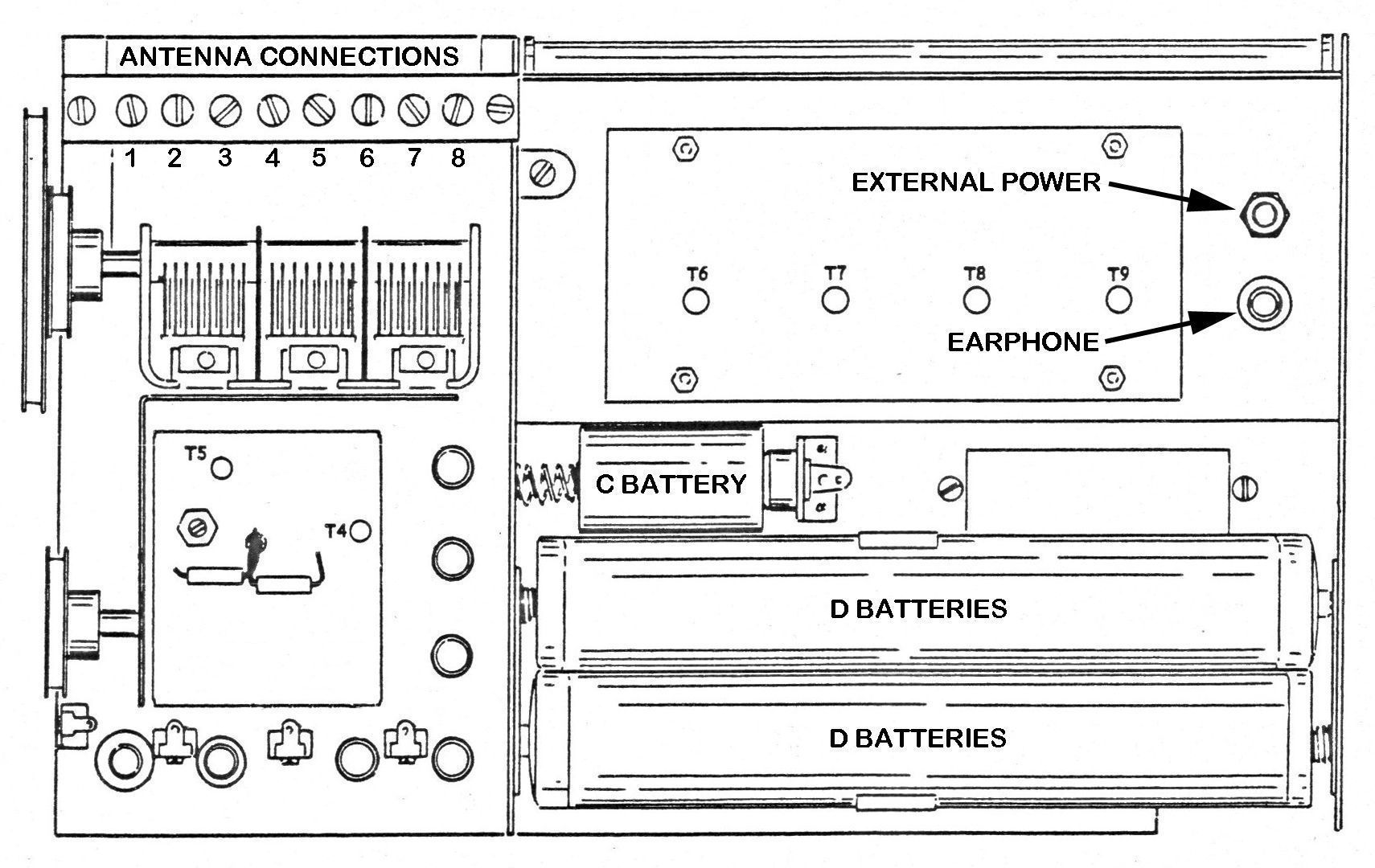
The rear panel opens for access to the batteries, earphone and external power connectors, and external antenna terminals. Refer to photos. The inside rear cover is screened with diagrams showing battery configuration and antenna connections.
The GR-43(A) circuit includes a battery saver that reduces battery drain “up to 35% for normal indoor listening, or provides full power for strong outdoor listening.” The battery saver works by selecting a different tap on the secondary of the audio output transformer, thereby changing the step-down ratio between the output transformer and the speaker. This causes a reduction in power of about 30% when lower volume can be used.
The GR-43(A) uses six D cells and one C cell (for the dial light). Heath noted that the D-cell pack could be charged and floated with the optional GRA-43-1 ”converter/charger” — what we now call a power cube, but some caution is advised here. First, if expendable batteries are installed, the use of an external power source could cause the batteries to leak, or worse. Modern alkaline batteries should never be recharged. Second, if rechargeable batteries are installed, it should be noted that the radio does not have a charging circuit. In the GR-43, any external power source is placed directly in parallel with the batteries. In the “A” version, a 22Ω resistor is placed between the power source and the batteries, which would limit the current to nominally 400 mA (with a 9-volt supply). In either case, the potential for overcharging the batteries significant.
The radio can be operated directly from the 9-volt power cube without batteries installed. Note that an external power source will not operate the dial light.
EXTERNAL ANTENNA CONNECTIONS
Refer to photos. An 8-terminal strip inside the rear panel provides connections for external antennas.
- AM / longwave / shortwave - An external for these bands may be connected to terminal 3. Heath recommended a random wire of between 50 and 100 feet in length. A ground wire should be attached to terminal 1.
- FM - A 72Ω antenna may be connected between terminals 1 and 2. Attach the shield to terminal 1. A 300Ω antenna may be attached between terminals 7 and 8.
Wires for antennas, power and earphones can be routed through small cutouts in the rear corners of the bottom panel, so that the rear panel may be fully closed.
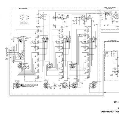
There are some significant cosmetic differences between the GR-43 and 43A. Refer to main photographs. Book project technical advisor Bob Eckweiler, AF6C, compared the schematics of the two versions and made these observations of changes in the 43A:
* The AM tuner board uses updated transistors, and adds oscillator voltage regulation.
* The AM IF board is identical except for a small bias resistor change.
* The FM tuner board uses updated transistors, and AGC was added to the mixer stage.
* The FM IF boards appear identical between models.
* The audio board uses a larger filter capacitor in the output stage (hum reduction with external power), and the diode used for temperature compensation was replaced with a transistor wired as a diode.
* A 22Ω resistor was added between the battery and the external power source.
AM Section
Tuning range: 150 to 400 kHz, 550 to 1600 kHz, 2 to 4 MHz, 4 to 9 MHz, 9..2 to 10.2 MHz, 11.2 to 12.4 MHz, 14.5 to 16.1 MHz, 16.8 to 18.8 MHz, and 20.2 to 22 MHz.
Sensitivity (at external antenna input for a 10 db signal-plus-noise noise ratio):
150 to 400 kHz - 12 µV
550 to 1600 kHz - 10 µV
2 to 4 MHz - 5 µV
4 to 9 MHz - 3 µV
9..2 to 10.2 MHz - 3 µV
11.2 to 12.4 MHz - 2 µV
14.5 to 16.1 MHz - 2 µV
16.8 to 18.8 MHz - 2 µV
20.2 to 22 MHz - 2 µV
IF frequency: 455 kHz
FM Section
Tuning range: 88 to 108 MHz
Sensitivity: 1.5 µV for 20 db quieting; 2 µV for 30 db quieting
IF Frequency: 10.7 MHz
General
Audio output (nominal): 500 mW; with battery saver on: 160 mW
Speaker: 4 x 6 inch, 3.2 Ω
Batteries: 6 D cells, 1 C cell (for dial light)
External power: 9 volts DC (will not operate the dial light)
Current drain (with fresh batteries and no signal applied):
FM: 18 mA
AM: 22 mA
Dial light: 300 mA
Solid state: (2) 155T1, (1) 154T1, (2) 2N1524, (4) 2N408, (1) 2N2495, (1) AF121, (1) 2N990, (4) 2N2654; Diodes: (2) 1N191, (2) 1N541, (1) 1N3182, (1) 1N2326
Photos, general information and specifications from "Heathkit: A Guide to the Amateur Radio Products," by Chuck Penson, WA7ZZE. Used with permission.