Note
QST, Jan 1937, p. 4.
Radio News, Feb 1937, p. 493.
QST, Mar 1937, p. 69.
Radio News, May 1937, p. 685. (special version adds 7.5 to 15 meters)
Radio's Master Encyclopedia, copyright 1937, p. H-59.
Radio, Jan 1942, p. 61.
Lafayette catalog number 73, p. 110.
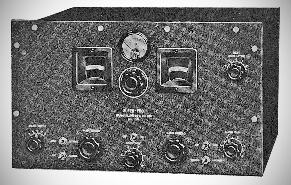
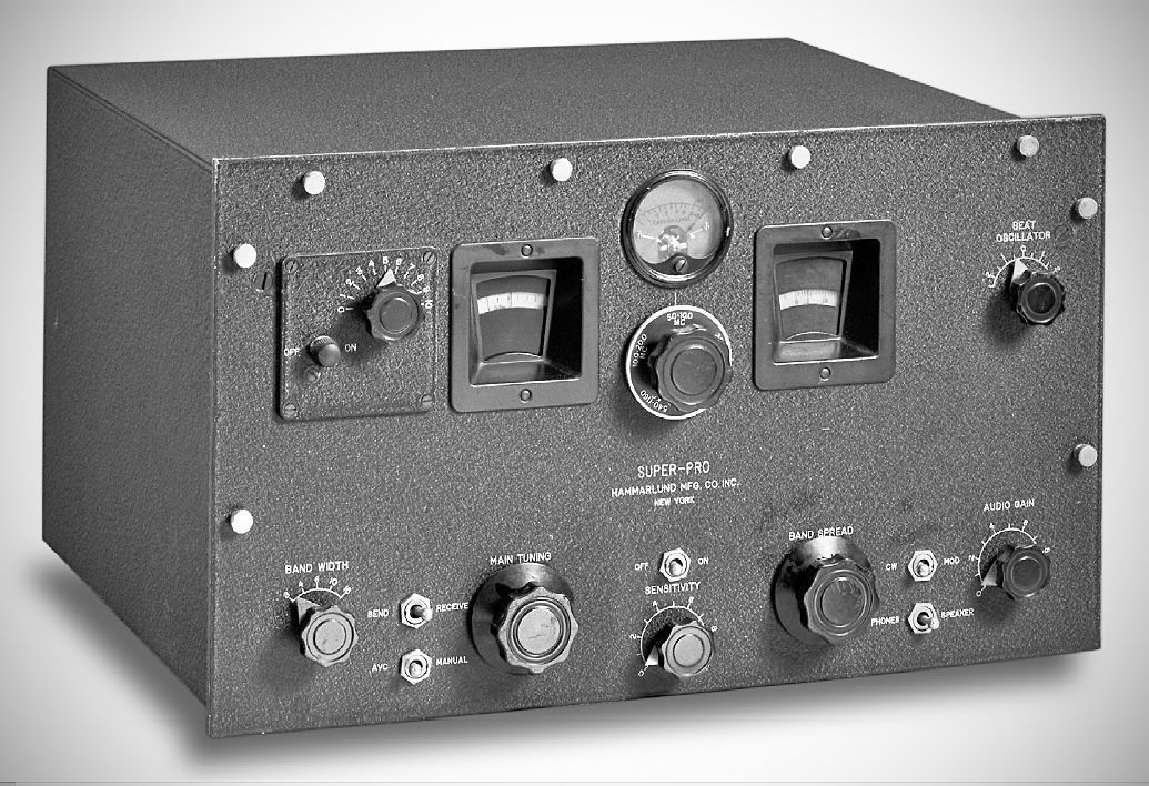
The Hammarlund SP-100 series, introduced in late in 1936, represents the immediate successor to the groundbreaking SP-10, the original "Super-Pro" receiver. Building upon the solid foundation laid by its predecessor, the SP-100 series refined the design and introduced key improvements, positioning itself as the next evolution in high-performance communications receivers from the renowned Hammarlund Manufacturing Company. While often seen as an interim model between the SP-10 and the more prolific SP-200 series, the SP-100 series played a crucial role in the Super-Pro lineage by incorporating features that would become standard for decades to come.
The 100 series consists of the SP-110 and the SP-120, and their variations. It is important to understand that these are not separate models, but the same model supplied with a different sized speaker. The SP-110 with a 10 inch speakers, and the SP-120 with a 12 inch.
The variations include:
SP-110 - 0.54 to 20 MHz (no crystal filter)
SP-110-X - as above, with crystal filter
SP-110-L - 100-400 kHz and 2.5-20 MHz (no crystal filter)
SP-110-LX - as above, with crystal filter
SP-110-S - 1.25 to 40 MHz (no crystal filter)
SP-110-SX - as above, with crystal filter
The SP-120s are the same as above, but with the 12 inch speaker. Also, both 110 and 120 were available for rack mounting.
Technically, "SP-110-X," for example, is not a model number. It was originally a code that described the receiver and its options. Over time, these designations became de facto model numbers. Admittedly, that is a subtle distinction.
The Hammarlund SP-10 and SP-100 were foundational models in the "Super-Pro" series, with the SP-100 representing a direct evolution and refinement of the original SP-10. While they shared the same core design philosophy of high-performance single-conversion superheterodyne reception with variable selectivity, the SP-100 introduced several key improvements.
Here are the primary differences between the SP-10 and the SP-100:
Tube Technology: One of the most significant changes in the SP-100 series was the transition from large-pin glass tubes to all-metal tubes in the critical RF, mixer, and IF stages. Tubes like the 6K7, 6L7, and 6J5 began to replace their glass counterparts (6D6, 6A7, 6C6) that were prevalent in the SP-10. This was a crucial advancement for several reasons: Superior Shielding: Metal tubes offered inherent and much more effective shielding against external interference and internal inter-stage coupling, leading to greater stability and reduced hum. Reduced Microphonics: Metal tubes were generally less susceptible to microphonic effects (mechanical vibrations being converted into electrical signals), which could be a problem in sensitive circuits. Durability: The metal envelopes made the tubes more rugged, an important consideration for military and demanding commercial environments.
While the SP-100 still used a mix of tube types (e.g., glass 76s and 42s in the audio section), the move to metal tubes in the front end marked a significant step forward in performance and reliability.
Controls and Ergonomics: SP-10: Had separate RF, IF, and AF gain controls, along with a tone control.
SP-100: Introduced a combined "Sensitivity Control" which replaced the separate RF and IF gain controls, simplifying operation for the user. It also featured new-style, smaller knobs with metal pointers, improving readability and aesthetics. The Tone control might have been eliminated in later SP-10 production and was not a primary feature of the SP-100.
Transformer Construction: SP-10 used a potted audio transformer (sealed in a compound). The variable coupling for the IF transformers was external to the main transformer can.
SP-100 saw a change in audio transformers to vertical mount-frame types. More significantly, the variable coupling mechanisms for the AVC (Automatic Volume Control) and Detector IF transformers were changed to fixed coupling, and their component boards were moved from under the chassis into the transformer cans. This streamlined the design and assembly.
Internal Component Brands/Materials: SP-10: Paper-wax capacitors were commonly Aerovox brand, sometimes intermixed with Cornell-Dubilier. Spacing rods in the RF tuning unit were typically brass.
SP-100: Paper-wax capacitors were usually Cornell-Dubilier "TIGER" brand, though intermixed with Aerovox. Spacing rods in the RF tuning unit changed to steel. These are subtle but indicative manufacturing changes.
Production Dates and Military Usage: SP-10: Introduced March 1936, production ceased around December 1936. Some very early military versions (SPA) may have slightly predated the commercial release. It had a relatively short production run.
The SP-100 series continued to be produced until the SP-200 took over as the primary Super-Pro model in late 1939. The SP-100 also saw military adoption, with specific variants developed for different frequency needs (e.g., SP-110-LX for low frequencies).
The core philosophy of the SP-100 series remained consistent with the SP-10: to deliver top flight sensitivity, selectivity, and stability for professional, military, and serious amateur radio applications. The fundamental architecture—a single-conversion superheterodyne receiver with a 465 kHz IF—was retained. However, Hammarlund engineers focused on addressing feedback from the field and integrating emerging technologies.
Key Features and Improvements:
Variable Selectivity via Variable-Coupled IF Transformers: Like the SP-10, the SP-100 retained the highly effective continuously variable IF bandwidth control, allowing adjustments from a very sharp 3 kHz to a wider 16 kHz. This was a defining characteristic of the Super-Pro line, offering unparalleled control over filtering.
Improved RF and IF Amplification: The use of metal tubes and refinements in circuit design allowed for even more stable and efficient amplification in the two RF stages and three IF stages. This contributed to excellent sensitivity across its operating range.
Calibrated Bandspread and Precise Tuning: The SP-100 maintained the highly accurate main tuning and bandspread dials, allowing for precise frequency selection. Hammarlund's renowned cam-operated bandswitching mechanism ensured robust and repeatable band selection.
High-Fidelity Audio: The 14-watt push-pull audio amplifier, utilizing type 42 tubes in the output stage, continued to provide strong and clear audio, making the SP-100 series suitable for both communications and high-quality shortwave broadcast listening.
Separate Power Supply: The external power supply remained a standard feature, essential for isolating hum and heat from the sensitive receiver circuitry and contributing to the overall stability and quiet operation of the receiver.
The Hammarlund SP-100, particularly its "LX" variants with the crystal filter, proved to be a very capable and well-regarded receiver. It represented a crucial stepping stone in the development of the Super-Pro line, demonstrating Hammarlund's responsiveness to technological advancements and user needs. Its short production run, overshadowed by the massive wartime production of the SP-200, makes the SP-100 somewhat rarer than its successor. However, it is highly valued by collectors for its historical significance as the bridge between the original Super-Pro and the wartime legend, embodying the robust construction and high-performance hallmarks that defined the Hammarlund name.
The SP-100 was not a revolutionary redesign but a significant evolutionary step from the SP-10. Its adoption of metal tubes in the front end was a crucial improvement for stability and shielding, and the integration of the crystal filter as an option marked its position as a more advanced and versatile communications receiver in the rapidly professionalizing field of radio.
Main Chassis
V1, V2: 6K7 (RF Amplifiers)
V3: 6L7 (First Detector / Mixer)
V4: 6J5 (High Frequency Oscillator)
V5, V6, V7: 6K7 (IF Amplifiers)
V8: 6J5 (Crystal Filter Stage / IF Oscillator - if equipped with crystal filter)
V9: 6H6 (Second Detector / AVC Rectifier)
V10: 6J5 (Beat Frequency Oscillator - BFO)
V11: 6J5 (AVC Amplifier / Delay)
V12: 6J5 (Noise Limiter / First Audio Amplifier)
V13: 6J5 (Audio Driver)
V14, V15: 42 (Audio Output - Push-Pull)
External Power Supply
5Z3 (High Voltage Rectifier)
80 (Bias Rectifier)
References
Review. Radio News, Feb 1937, p. 474.
Review. Radio News, Mar 1937, p. 539.
Brief review: Radio, Jan 1938, p. 100.
Discussion related to 10 meter performance. Radio News, May 1937, p. 661.
Console version. Radio News, Nov 1937, p. 290.