Note
SB-220 1970-1978 $349.95
SB-221 1978-1983 $579.95
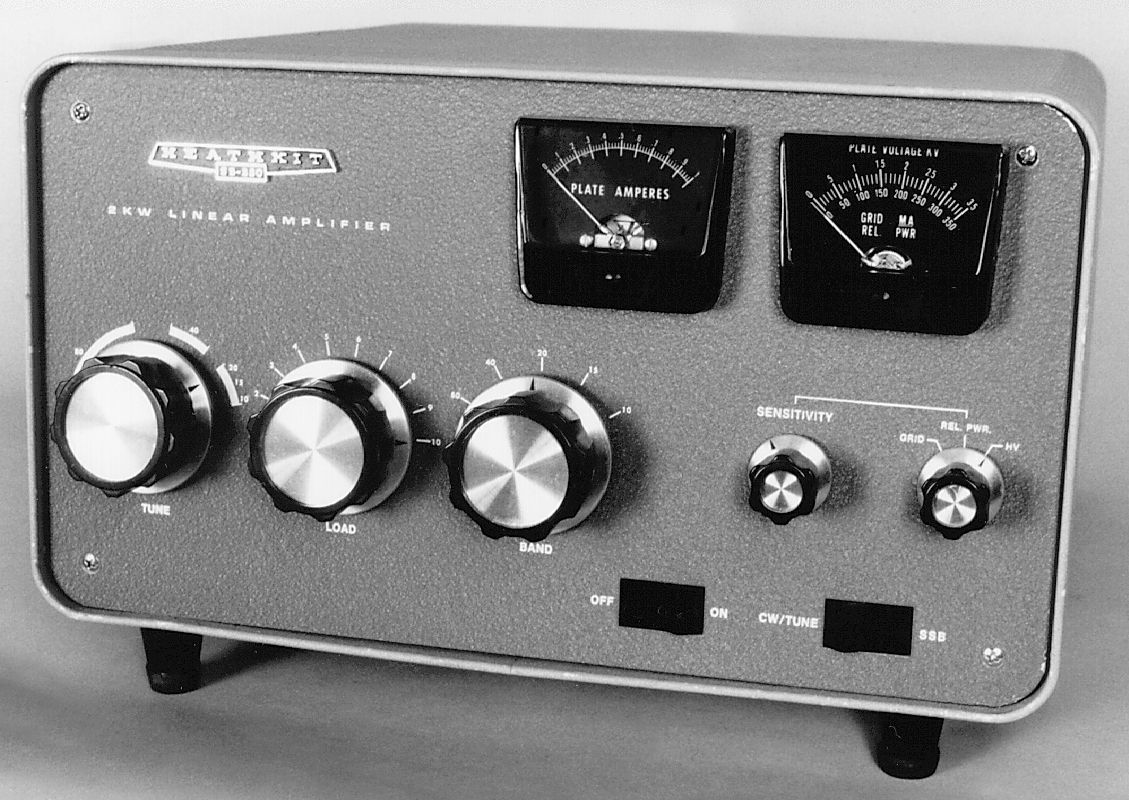
The SB-220 is probably the second most popular amplifier on the planet, right behind the SB-200.
The SB-220(221) is rated at 2000 watts input PEP and 1000 watts CW using a pair of fan-cooled, instant-on, 3-500Z tubes running in parallel, and operated close to ground potential in class B. The amplifier can be driven with as little as 65 watts, but to realize full output power requires at least 100 watts of drive.
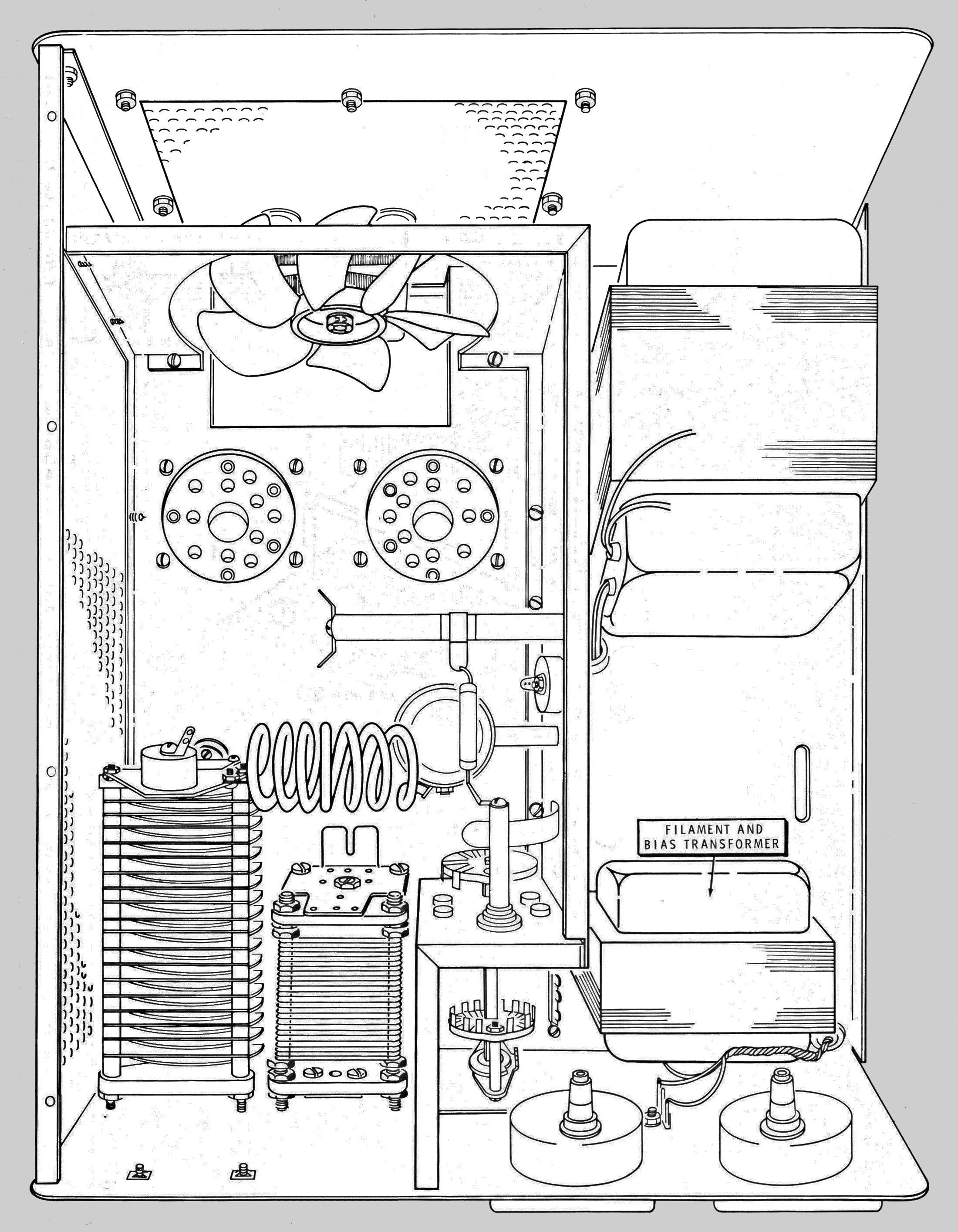
A double shielded RF deck keeps the TVI potential to an minimum. The amp features a built-in, solid-state power supply with a circuit breaker (on the rear panel), safety interlocks, full metering, an ALC connection, pre-tuned broadband Pi-input, and Zener diode regulated bias to reduce plate idle current and help reduce operating temperature.
The input impedance is about 50Ω. There is no built-in SWR bridge, as in the SB-200. The only difference between the SB-220 and the SB-221 is frequency coverage. The SB-220 covers 80-10 meters. The SB-221 covers only 80-15 meters. This change was dictated by new regulations governing the manufacture of linear amplifiers.
Front panel controls include rocker type switches for main power and mode (SSB/CW), tune, load, and band-switch controls, relative power sensitivity, and meter function. There are two illuminated meters. One reads plate current and the other can be switched between grid current, relative power, and high voltage.
Rear panel connections include a ground post, RCA jacks for antenna relay and ALC, and SO-239s for both RF input and output. The SB-220(221) is designed for use with 50Ω loads.
The SB-220 was not originally quite as reliable as the 200(201) as far as the power supply is concerned, and low high-voltage due to blown diodes in the stack are common. A simple test: when run from 240 VAC in the SSB mode, the high-voltage should push the meter right up to the end of the scale and perhaps right to the peg. A reading much less than full scale may indicate one or more bad diodes.
Also, the Zener diode regulating the bias is easy to damage with any significant arcing in and around the coils and caps. Plate idle current should be around 75 ma. A higher reading may indicate a bad Zener. A modification (a larger Zener diode) was offered to fix this issue.
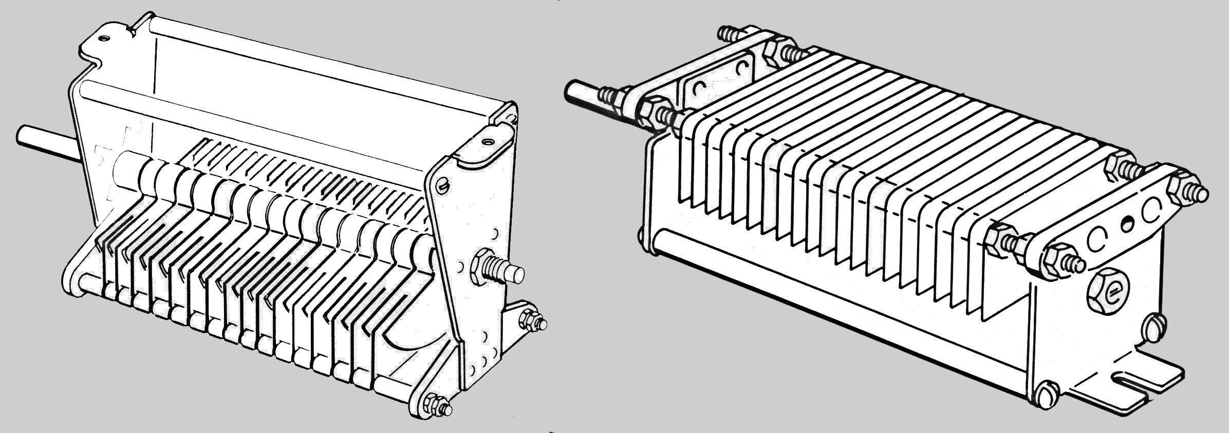
The problem users complained about most frequently was arcing in the tuning capacitor. Heath eventually did a redesign to fix the problem in later model SB-220s and in the SB-221. The company also offered a modification kit for existing SB-220 owners. The fix, and the modification kit, involved a handful of parts and a new tuning capacitor.
It is impossible to determine which tuning capacitor is installed in any specific amplifier without removing the cabinet and the top RF shield, but there are distinct physical differences between the original and replacement tuning capacitors that make identification easy. To determine which capacitor has been installed in a specific amplifier, refer to Figure 1.
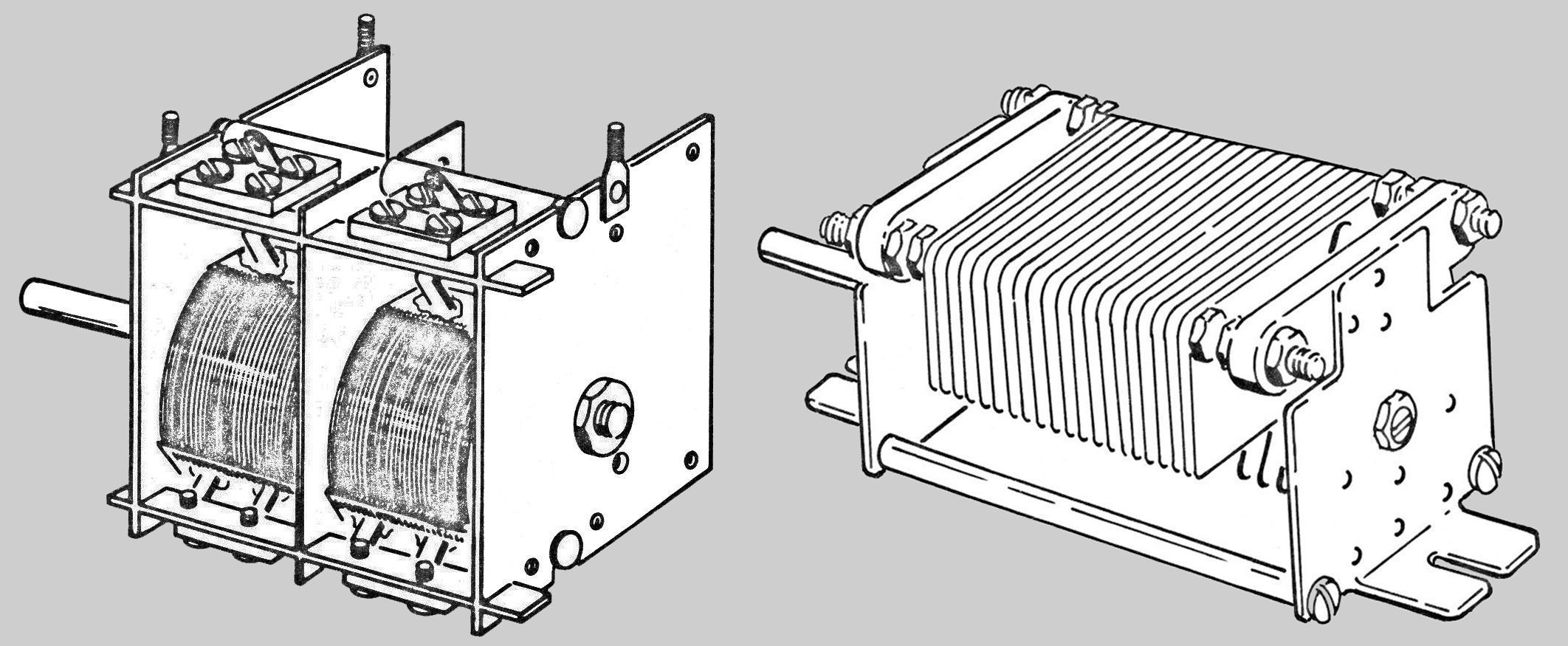
Even before Heath replaced the tuning capacitor, it replaced the loading capacitor. There were no problems with the original loading capacitor, it was mostly about a lower cost part. The original loading capacitor was a two-gang type. It was replaced with a single-gang part. Figure 2 illustrates the difference between the two parts.
The SB-220(221) can be wired for either 120 VAC (20 amp max) or 240 VAC (10 amp max) operation. 240 VAC operation is highly recommended.
The SB-220(221) are styled to match the other SB-series gear and wear the classic two-tone green wrinkle finish paint. The amplifier remains as good a value today as when it was last sold in 1983. The SB-220 is in greater demand by virtue of its 10 meter coverage.
Volumes have been written on modifications for these amplifiers. An online search will return dozens of hits.
Note: A modification of the transceiver is required for use with the HW-12, HW-22, and HW-32. Refer to HW-12 for details.
Warning: Lethal voltages present when operating.
References:
Review. QST. Aug 1970, p. 45.
Review. 73 Amateur Radio. Jul 1971, p. 77.
Review (SB-221). QST. Mar 1980, p. 43.
Review. CQ (SB-221). Feb 1983, p. 36.
Use with Swan 500. CQ. Jul 1972, p. 12.
Use on 6 meters. QST. Dec 1974, p. 47.
Improved CW operation. Ham Radio. Nov 1977, p. 99.
Better parasitic chokes, low power on 10 meters. QST. Nov 1978, p. 40.
Upgrading. QST. Feb 1979, p. 20.
Upgrading (more on). QST. Arp 1979, p. 27.
Upgrading (more on). QST. Jul 1979, p. 44.
Upgrading (more on). QST. Nov 1979, p. 56.
Upgrading (more on). QST. Feb 1980, p. 44.
Solid-state QSK for. QST. Jan 1980, p. 25.
Add a standby mode. 73 Amateur Radio. Oct 1980, p. 197.
Inrush current limiter. QST. Aug 1982, p. 49.
Improved inrush current limiter. QST. Aug 1985, p. 41.
Balanced grid circuit for. QST. Aug 1986, p. 38.
Tips. QST. Aug 1986, p. 37.
Power supply modifications. CQ. May 1987, p. 48.
Use with solid state transceivers. QST. Jan 1988, p. 45.
“No holes” STBY switch. QST. Sep 1988, p. 45.
Improvements. QST. Feb 1989, p. 42.
Circuit improvements, pt 1.. QST. Nov 1990, p. 25.
Circuit improvements, pt 2. QST. Dec 1990, p. 41.
Panel light problems with 160 meter mods. QST. Feb 1991, p. 38.
General information about SB series. Electric Radio. Sep 2016.
Band coverage:
SB-200: 80, 40, 20, 15 and 10 meters
SB-221: 80, 40, 20 and 15 meters
Drive power required: 100 watts
Maximum power input:
SSB: 2000 watts PEP
CW: 1000 watts
RTTY: 1000 watts
Duty cycle:
SSB: continuous voice modulation
CW: continuous (maximum key down 10 minutes)
RTTY: 50% (maximum transmit time 10 minutes)
Third order distortion: –30 db or better
Input impedance: 52Ω unbalanced
Output impedance: 50Ω unbalanced (SWR 2:1 or less)
Circuit breakers: two, 10 amperes
Power requirements:
120 VAC, 50/60 Hz, 20 amps maximum OR
240 VAC, 50/60 Hz, 10 amps maximum
Tubes: (2) 3-500Z
Photos, general information and specifications from "Heathkit: A Guide to the Amateur Radio Products," by Chuck Penson, WA7ZZE. Used with permission.