Note
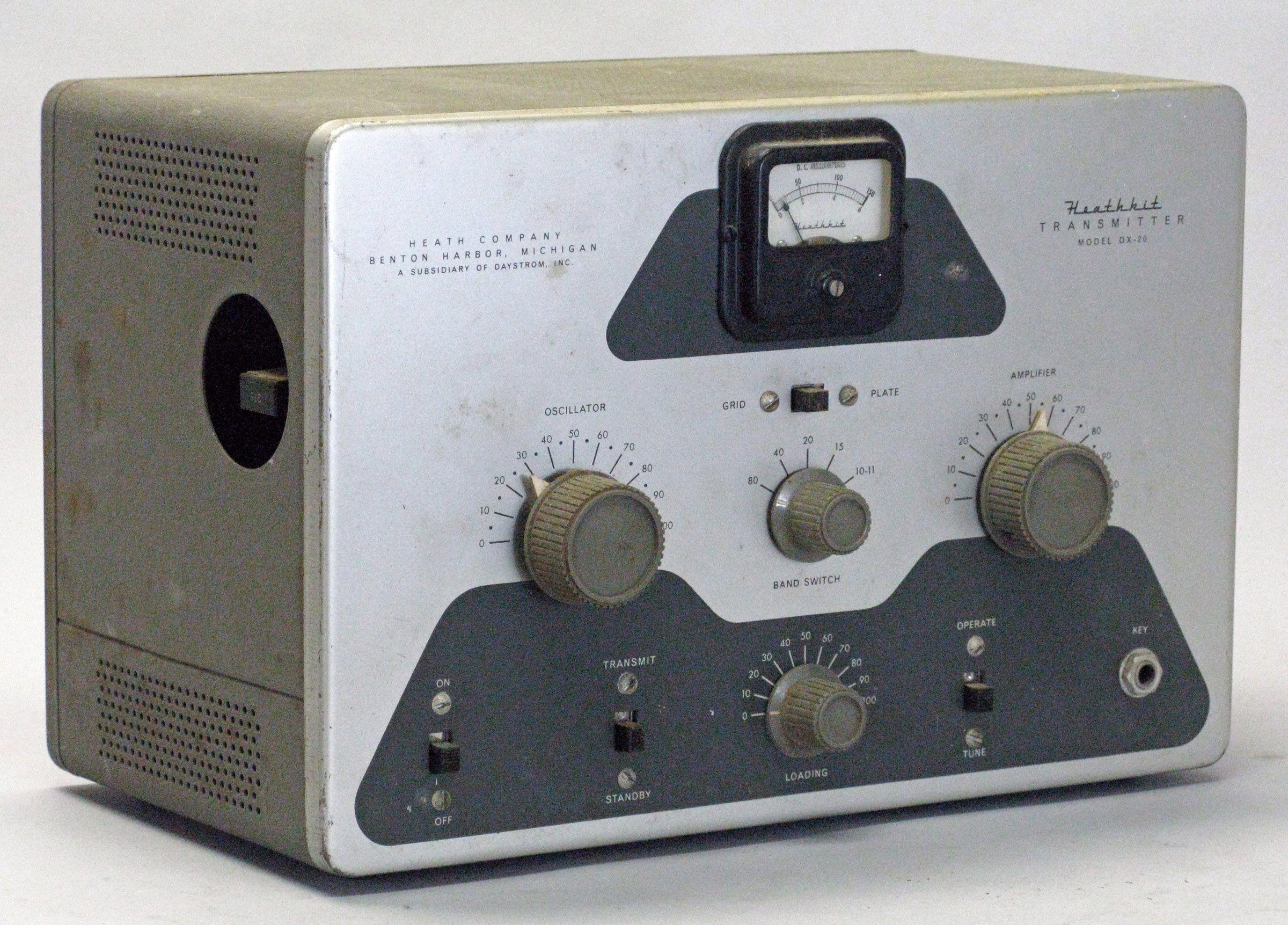
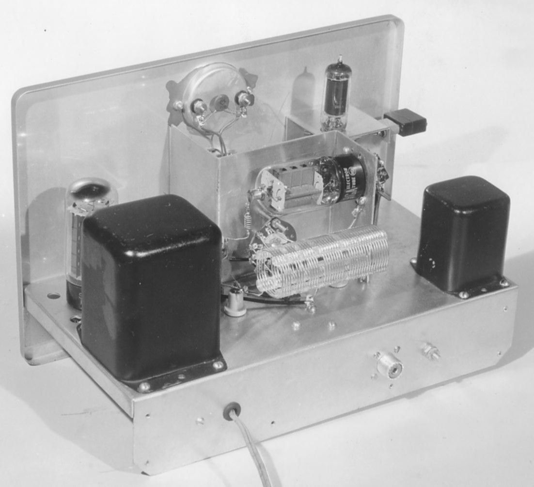
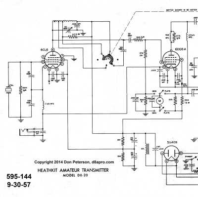
The DX-20 was the replacement for the AT-1 and was arguably one of the most successful transmitters Heath ever made. It was more than just an AT-1 in a new box; it was redesigned from top to bottom. It was still a three-tube design, but its Colpitts 6CL6 gave it a more stable signal, and its 6DQ6 gave it twice the power of the AT-1—about 50 watts. The DX-20’s pi network output allowed the user to match anything from 50 to 1000Ω and gave it the reputation of being able to load into bed springs. Its two-tone gray styling made it look like a miniature DX-100.
The DX-20 covers from 80 through 10 (including 11) meters. While the DX-20 can be used with the VF-1 VFO, there are no provisions for getting power to it as with the AT-1. Heath recommended an external power source for a VFO. And unlike the AT-1, the DX-20 makes no provisions for a modulator. These features were eliminated in an effort to to reduce the cost and provide a lower priced alternative to the DX-35.
Note that an extra pair of contacts to accommodate an antenna relay are provided on the TRANSMIT–STANDBY switch.
Particular attention should be paid to the panel meter as it is often found to have been replaced with a non-original. Note that the DX-20 uses a black iron vane meter with a zero adjust, and has the Heathkit logo printed on the meter face. This is the same meter used in the DX-35, but is not the same one used on the AT-1.
It is impossible to say how many DX-20s were sold, but it was probably several times the number of AT-1s. In 1961 the DX-20 was replaced by the HX-11. Refer to HX-11 for additional discussion. Caution: Not fuse protected.
Although deleted from the catalog after 1960, the DX-20 appeared once more in a discontinued-item sale flyer mailed in April 1962.
CAUTION: Not fuse protected.
CRYSTAL CONSIDERATIONS
Band Fundamental Crystals
80 m 160 or 80 m
40 m 80 or 40 m
20 m 80 or 40 m
15 m 40 m
10 m 40 m
References:
Review. CQ. Apr 1957, p. 96.
Review. Popular Electronics, Apr 1957, p. 80.
Modulator for. Popular Electronics, Aug 1957, p. 53.
Brief description. Radio News, Sep 1957, p. 126.
Use on 6 meters. 73 Amateur Radio. Oct 1962, p. 10.
Use on 30 meters with VF-1. QST. Jan 1986, p. 49.
Power transformer reliability. Electric Radio. Jun 2017.
Revisiting. Electric Radio. Apr 2019.
History, repair, mods. Electric Radio. Jun 2019.
RF input power: 50 watts CW
Output impedance: 50-1000Ω
Output coupling: Pi network, SO-239
Operation: crystal or external VFO
Power requirements: 120 VAC, 50/60 Hz, 160 watts
Tubes: (1) 5U4, (1) 6CL6, (1) 6DQ6
Photos, general information and specifications from "Heathkit: A Guide to the Amateur Radio Products," by Chuck Penson, WA7ZZE. Used with permission.