Note
The SB-650 was another very popular accessory for the SB and HW series of receivers and transceivers and caused quite a stir when first released. It was, however, released about midway through the life of the SB-102 and was made only until the release of the digital readout SB-104 in 1975. The resulting short production life has made the 650 one of the more sought after pieces in the SB series.
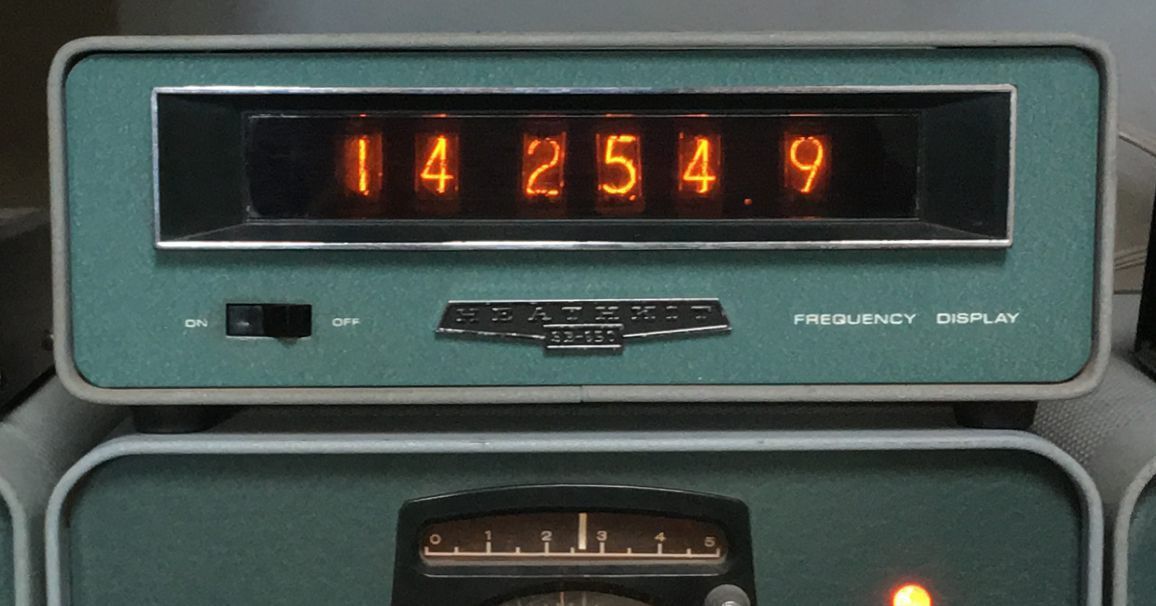
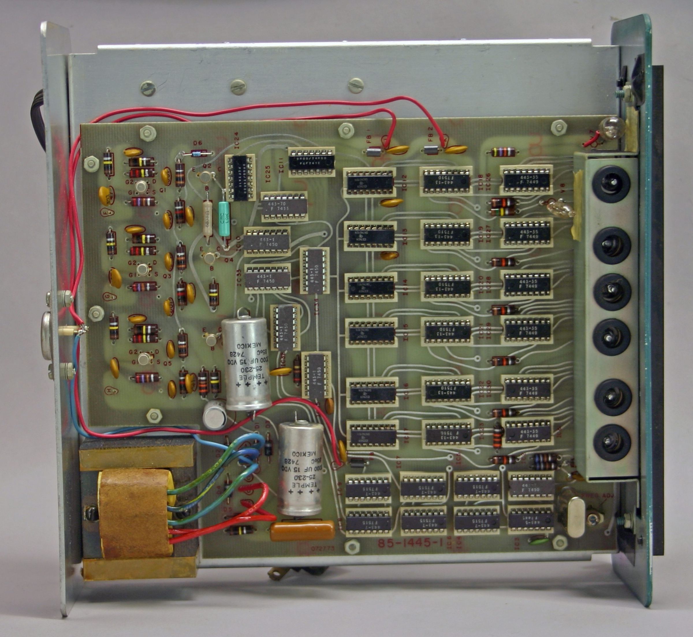
Except for the readout tubes, the SB-650 is a fully solid state device and is built on one large double-sided PC board. It uses 36 ICs, six transistors, and a handful of diodes. The display uses six Nixie tubes and provides a readout to 100 Hz.
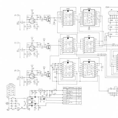
The SB-650 does not read the operating frequency directly but instead derives the frequency from three signals picked off of the receiver or transceiver. These signals are the beat frequency oscillator (BFO), the linear master oscillator (LMO), and the heterodyne frequency oscillator (HFO), and getting them out of the SB or HW transceivers and receivers requires a modification to the units which includes the drilling of up to three rear panel holes for the installation of RCA jacks, and some attendant internal wiring.
Note that when used in combination with the SB-400 or 401 transmitter, the transmitter requires the addition of a small choke. The 650’s manual is very clear about the procedure for all of the SB and HW family. Important: You will need the manual to do the installation.
Since the SB-650 depends on three signals, the unit will not read properly under certain conditions. For example, when used with the SB-300, 301, or 303, it will not read correctly if the receiver is placed in the AM or RTTY mode since the BFO signal is not present in those modes. When operating CW, the 650 will read the receive frequency but will indicate the 1 kHz BFO offset upon key down.
Heath did not recommend using the SB-650 with other brands of receivers, but it is often possible to do so with a few modifications. Use with the Drake 4-line, Yaesu FT transceivers and Collins S-line is fairly straightforward. See QST magazine, January 1973, p. 52 for details. Also see Ham Radio magazine. June 1973, p. 40.
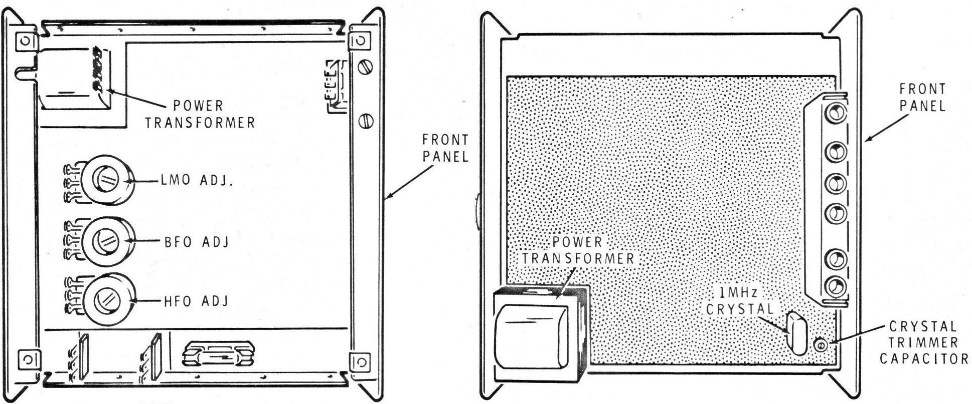
The only front panel control is an on/off rocker switch. There are four internal controls. Refer to illustration. Three of these are potentiometers used to set the levels of the BFO, LMO, and HFO signals. The fourth is a trimmer cap used to calibrate the unit. Calibration is very simple. Just tune the receiver to CHU (7.3350 MHz) or WWV (at 15.0000 MHz) and adjust the trimmer for the correct reading.
The only rear panel connections are three RCA jacks, one for each signal. Interconnecting cables should be made from RG58A/U or equivalent and should be no longer than 18 inches.
While a readout to 100 Hz is technically possible, many units have a enough jitter in the right-most digit to render it meaningless. Maximum stability requires at least a 10-minute warm-up.
If the unit you bought doesn’t work right, the first course of action should be to re-seat the ICs. With time, the pin/socket junctions may oxidize, causing erratic operation. Readjusting the input level controls will also help.
The SB-650 manual is full of trouble-shooting tips and has dozens of voltage and wave form charts to assist you. Most of the ICs are common TTL devices and should be relatively easy to find should any need to be replaced.
The Nixie display tubes are National NL-1220 or Burroughs B-5859A miniatures with wire bases—not the plug-in type. Finding these tubes could present a challenge.
Caution: The SB-650 requires plenty of ventilation and should not be placed directly on top of heat-producing equipment. The unit is finished in the standard SB two-tone green wrinkle.
References:
Review. QST. Aug 1972, p. 56.
Review. CQ. Oct 1972, p. 58.
Use with other receivers. QST. Jan 1973, p. 52.
Use with other receivers (more on). QST. Mar 1973, p. 65.
Use with other receivers. Ham Radio. Jun 1973, p. 40.
Use with FT-101. QST. Mar 1977, p. 24.
Use with Allied AX-190. QST. Sep 1978, p. 37.
Frequency range: 3 to 40 MHz
Frequency display: 6 digits
Maximum viewing distance: 30 feet
Maximum input signal: 5 volts
Accuracy: within 100 Hz ±1 count after 20 minute warm up
Compute time: 160 milliseconds
Input impedance: 2000Ω
Internally generated spurious signals: less than 0.25 µV equivalent
Crystal (clock) frequency: 1 MHz
Crystal aging rate: less than 10 ppm per year
Ambient crystal stability: 10 ppm from +10 to +65 C
Operating temperature range: 0 to +40 C
Storage temperature range: –55 to +80 C
Power requirements: 120/240 VAC, 50/60 Hz, 15 watts
Photos, general information and specifications from "Heathkit: A Guide to the Amateur Radio Products," by Chuck Penson, WA7ZZE. Used with permission.