Note
SB-104 1974-1977 $699.95
SB-104A 1977-1982 $669.95
The SB-104 and 104A use more than 275 solid-state devices including 31 ICs. The selling points were these: fully solid-state including the finals, broadband/no tuning, and a digital display.
The SB-104 was Heath’s first major stumble. There were are number of factors that contributed to the problems with the rig, but two stand out. First, digital and broadband technology were relatively new and unfamiliar to Heath. Second, the company had rushed the project to achieve a Christmas release. What Heath ended up putting in the catalog was essentially a prototype. The receiver was full of birdies, the transmitter was dirty, the final transistors would not take a high SWR (not even briefly), the CW waveform was much too abrupt, TR switching wasn’t clean, the digital display had the jitters, and the list goes on and on.
After four years of re-engineering and many modifications, most (but not all) of these problems were solved with the release of the SB-104A. A modification kit (SBM-104-2) was offered to owners of the 104 to upgrade their units to the 104A. Therefore, it is important to understand that there are essentially three versions of the SB-104. These include the original SB-104, and two versions of the SB-104A. There are SB-104A units that started life as an SB-104 and were upgraded with factory modifications installed by the user, and there are factory original SB-104As.
How to Tell Which SB-104A You Have
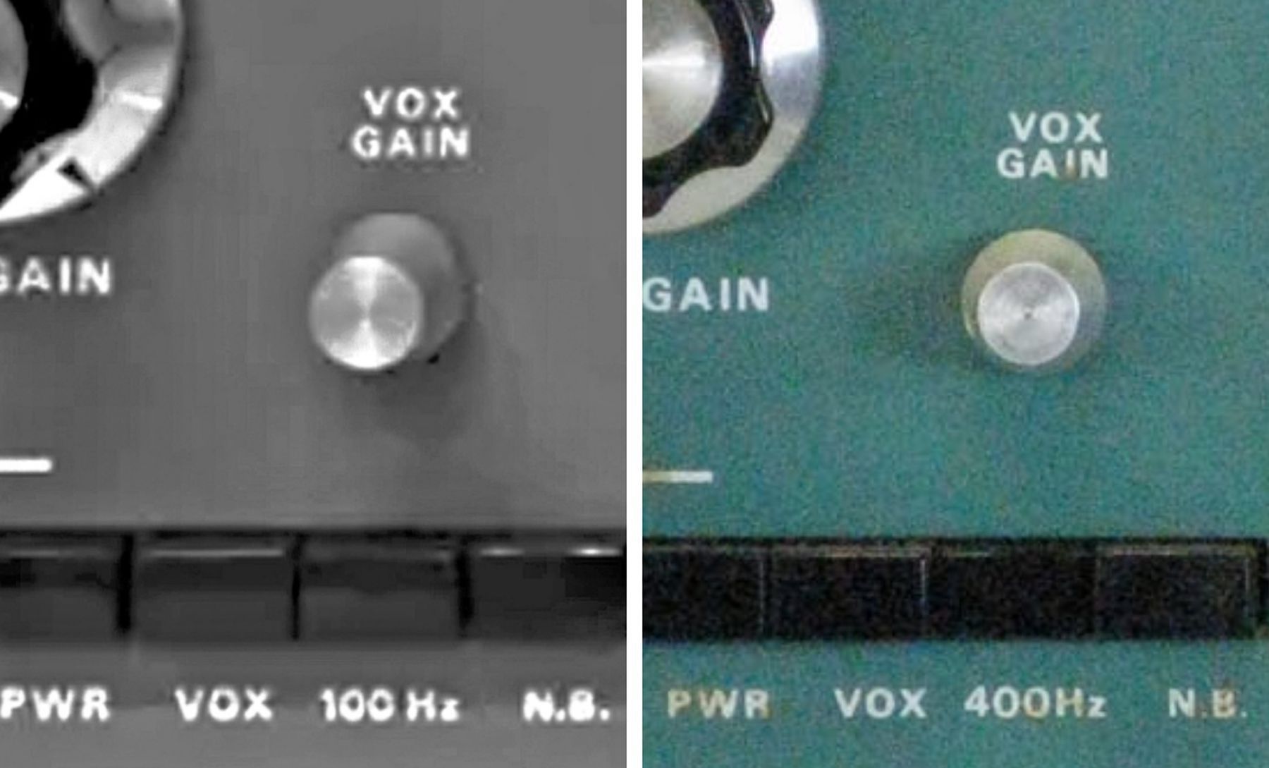
Refer to photo. Since the upgrade included a new front panel plastic name strip that says "SB-104A," you can not rely on what the front panel says. Instead, look at the pushbutton directly below the VOX gain control. If this button is labeled “100Hz,” the unit is an SB-104 that has been upgraded. If the button is labeled “400Hz,” it is a factory original SB-104A.
The purpose of the 100Hz button was to turn the 100Hz frequency display digit on or off. When the factory SB-104A was released the 100Hz button was repurposed to switch the (optional) CW filter in and out. (Refer to HW-104 for the location of the CW crystal filter.) In the original SB-104, the CW filter was switched in whenever the mode switch was set for CW. This proved to be inconvenient when tuning around the band prior to engaging in a QSO.
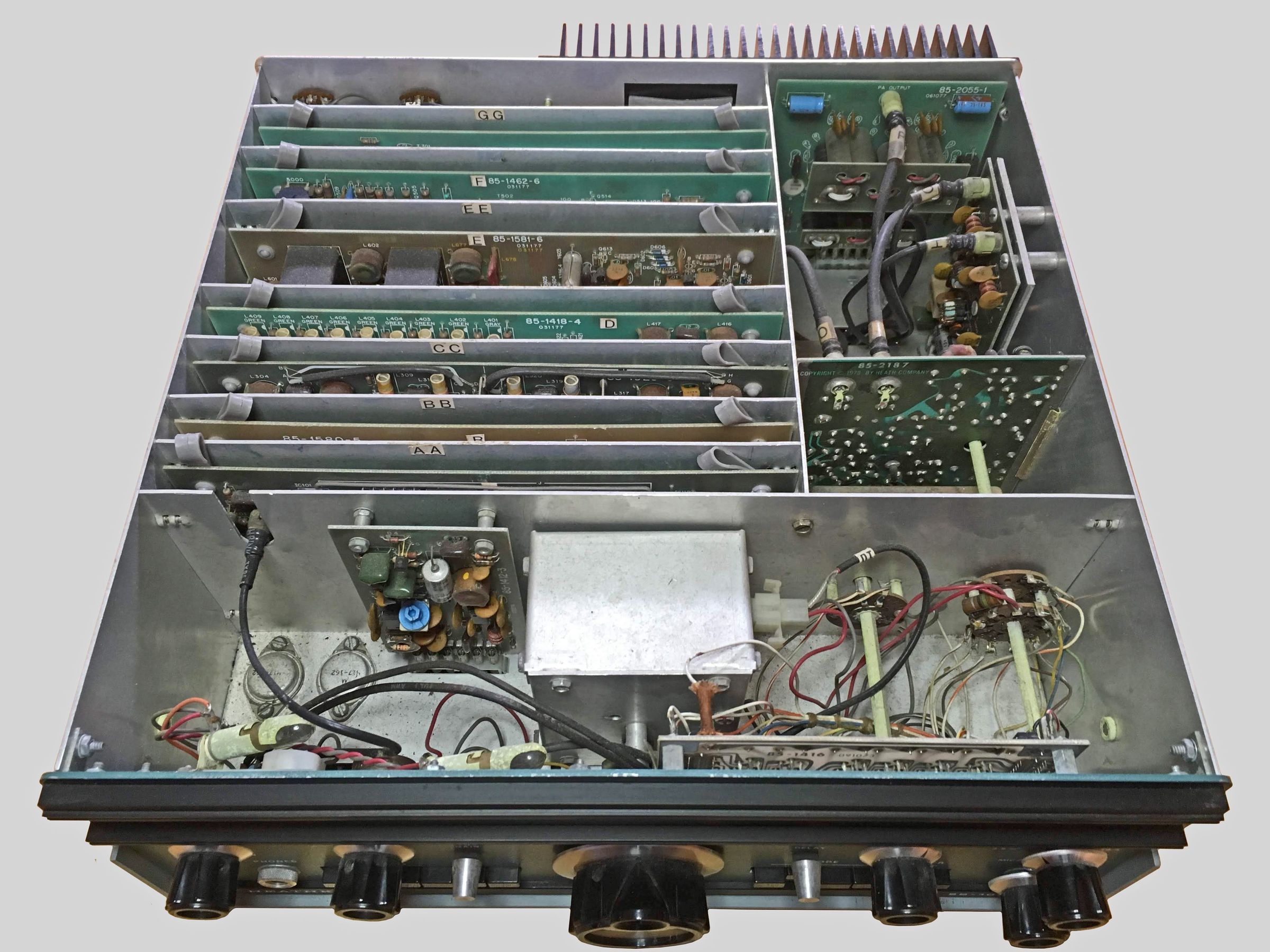
The SB-104(A) covers 80-10 meters (but no WARC bands) plus 15 MHz WWV and runs about 100 watts PEP and CW output. The 104(A) will run USB, LSB, and CW and is built on 15 PC boards. Ten of these boards plug in to the main chassis, and seven can be extended for ease of servicing and adjustment while the transceiver is operating. Refer to Figures 2A and 2B. An extender board was provided, but very often has long since gone missing.
Features include a broadband no-tune design, built-in CW sidetone, push-button selection of most functions including meter function, VOX, mode, tune, and power on/off. Caution: The tune button is intended only for the tuning of antenna tuners. Do not exceed 30 seconds in the tune mode with high power. There is also a QRP mode that yields about one watt of output power.
T/R switching is accomplished with a mechanical relay, so true QSK is not possible.
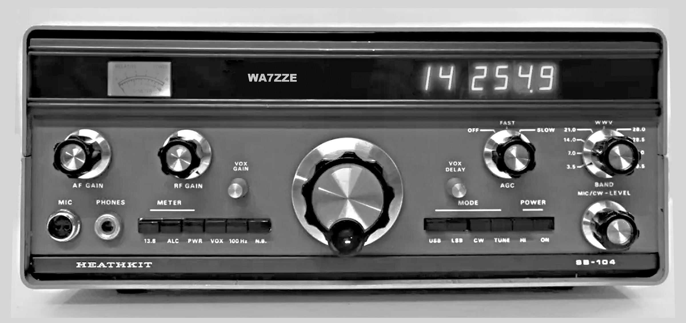
Front panel controls include the aforementioned push buttons, AF and RF gain, AGC fast/slow/off, VOX gain and delay, band switch, mic/CW level, and main tuning. The main tuning knob is a “spinner” type and slews at the rate of 30 kHz per revolution. In addition to the seven-segment neon type digital display, the front panel also includes a meter that reads both S-units and relative power, and a space for the call letters of the station. (The clever person should be able to figure out a way to replace the call letters with his or her own, or simply block it out.)
The readout tubes in the digital display are Beckman/Sperry SP-352 Panaplex tubes. These are the same type used in Heath’s GC-1094 and GC-1092 digital clocks. It would also be possible to use tubes from the GC-1005 digital clock or ID-1590 wind speed and direction display (SP-752), but this type does not have the “keep-alive" electrodes that prevent occasional flickering of digits. On the other hand, stripping a clock for the display tubes might be considered by some people to be a criminal act. Let your conscience be your guide.
Rear panel controls include VOX anti-trip, sidetone level, and a switch for selection of separate or common antennas. Rear panel connections include RCA jacks for key, phone patch in and out, linear amp ALC input, a 4Ω speaker, receiver audio input, VFO input and output, IF output, driver output, and two spares. There is also a ground post, an 11-pin power plug, and an accessory socket (which includes relay output).
An optional noise blanker was available (SBA-104-1). It is a small, plug-in circuit board. If present, it is located on the left side of the transceiver, just behind the front panel, and adjacent to the VFO. Refer to Figure 3 for the location of the noise blanker. Note: The noise blanker front panel pushbutton switch is present whether or not the noise blanker itself is installed.
The SB-104A was introduced in the Christmas 1977 catalog. The headline read, “Now with improved sensitivity and reduced assembly time," though it might just as well have read, “Now pretty much works right, mostly.” Most, but not all, of the bugs in the 104 had been fixed in the 104A. Among the fixes was a redesigned and pre-assembled front-end board (board G) that improved receiver sensitivity from 1.0 µV to 0.5 µV. (Bear in mind that the sensitivity of the SB-102 was better than 0.35 µV.) The transmitter IF board (board C) was also resigned and factory assembled, and the VFO filter board was redesigned to solve the display jitter problems.
The birdies heard all over the bands were due in large measure to the DC to DC high voltage converter used to operated the display tubes. The converter is located directly behind the ALC/low pass filter board. Hash from the converter leaked into the weak signal path and showed up all over the place. Heath attempted to reduce the birdies with additional shielding.
An interesting side note: the output power specification is 100 watts ±1 db, which means the output can range from 80 to 125 watts and still be considered in spec.
The SB-104(A) comes with both an assembly and an operations manual—try to get them both. Also try hard to get the card extender boards that came with the radio. They are essential for working on the rig.
Bottom line: The original SB-104 suffered from a list of problems so long they cannot all be described here. More than 80 service bulletins were issued for the transceiver. Don’t expect one to work well, if at all. Upgraded SB-104s should be regarded with suspicion. The factory original SB-104A, on the other hand, will probably perform satisfactorily.
The lower cost HW-104 used most of the same components as the SB-104, but lacked the digital display.
The transceiver is designed for use with the HP-1144 power supply. For power supply connections see HP-1144(A). See page nn-nn.
The unit uses the classic SB two-tone green wrinkle finish and SB series knobs. The SB-104(A) was an expensive endeavor for Heath and one from which it never saw a profit. Caveat emptor.
Typical Operating Characteristics
* The relay may activate briefly when you turn the transceiver on.
* The relay may activate briefly when you switch modes and the VOX pushbutton is depressed.
* You may hear a pop from the speaker when you change modes.
* You may encounter interference from a station operating between 8.395 and 8.895 MHz. You can usually remedy this condition by adjusting coil L715 on the receiver front end board (board G). Adjust this coil for minimum S-meter reading when the interfering station is transmitting.
References:
Review. CQ. Aug 1975, p. 28.
Review. QST. Dec 1976, p. 42.
Relay hangs up. QST. Dec 1977, p. 45.
Improved noise blanker. QST. Jan 1977, p. 39.
Improved noise blanker. QST. Aug 1977, p. 33.
Improved noise blanker (feedback). QST. Apr 1979, p. 47.
Improving the SB-104/SB-644 combo. QST. Aug 1979, p. 28.
Improving the SB-104/SB-644 combo (feedback). QST. Sep 1979, p. 23.
Improving the SB-104/SB-644 combo (feedback). QST. Mar 1980, p. 49.
Improving the SB-104/SB-644 combo (more). QST. May 1980, p. 41.
Modification PC board etching pattern. QST. Jan 1980, p. 54.
Adding RIT. QST. Jan 1980, p. 16.
Adding RIT (feedback). QST. Mar 1980, p. 49.
Improved receiver performance. Ham Radio. Apr 1980, p. 78.
Improvements. QST Dec 1980, p. 53.
Improvements. QST. Mar 1982, p. 20.
Improvements. QST. May 1982, p. 43.
Improvements. 73 Amateur Radio. Aug 1998, p. 10.
RECEIVER
Sensitivity:
SB-104: less than 1.0 µV for 10 db signal plus-noise-to-noise ratio
SB-104A: less than 0.5 µV for 10 db signal plus-noise-to-noise ratio
Selectivity:
SSB: 2.1 kHz minimum at 6 db down, 5 kHz maximum at 60 db down (2:1 nominal shape factor)
CW (filter optional): 400 Hz at 6 db down, 2 kHz at 60 db down
Overall gain: less than 1.0 µV for 0.5 watts audio output
Audio output: 2.5 watts into 4Ω, 1.25 watts into 8Ω, at less than 10% THD
Headphones: low impedance (4 to 8Ω)
AGC: less than 1.0 millisecond attack time, switch selectable release time of 100 milliseconds, 1 second, and OFF
Intermodulation distortion: –60 db
Image rejection: –60 db
IF rejection:
–60 db below 8.395 to 8.895 MHz
–55 db below 3.395 MHz
Internally generated spurs: below 2.0 µV equivalent, except at 3.65, 3.74, 14.24, 21.2, 28.46, 28.9 and 29.33 MHz
TRANSMITTER
Output power (50Ω nonreactive load):
high power: SSB, 100 PEP ±1 db; CW, 100 watts ±1 db
low power: SSB, 1 watt PEP minimum; CW, 1 watt minimum
Output impedance: 50Ω, less than 2:1 SWR
Carrier suppression: 50 db down from 100 watt single-tone output at 1000 Hz
Unwanted sideband suppression: 55 db down from 100 watt single-tone output at 1000 Hz
Harmonic radiation: 40 db below 100 watt output
Spurious radiation: –40 db within ±4 MHz of carrier, –60 db greater than ±4 MHz of carrier, except on the 10 meter band, –50 db
Third order distortion: 30 db down from two-tone output at 100 watts PEP
Sidetone: about 700 Hz
Mic input: high impedance with a rating of –45 to –55 db; approximately 25kΩ.
GENERAL
Frequency coverage (MHz): 3.5 to 4.0, 7.0 to 7.3, 14.0 to 14.5, 21.0 to 21.5, 28.0 to 29.7, (15.0 to 15.3 receive only)
Frequency stability: less than 100 Hz/30 min. drift after 30 min. warmup, less than 100 Hz drift for ±10% change in line voltage
Modes: USB, LSB, CW
Audio frequency response: 350 to 2450 Hz ±75 Hz (6 db bandwidth)
Tuning backlash: 100 Hz
Phone patch impedance: 4Ω output to speaker; high impedance output to transmitter
Power requirements:
13.8 VDC nominal (16 VDC maximum)
receive: 2 amps
transmit, high: 20 amps
transmit, low: 3 amps
Photos, general information and specifications from "Heathkit: A Guide to the Amateur Radio Products," by Chuck Penson, WA7ZZE. Used with permission.