Note
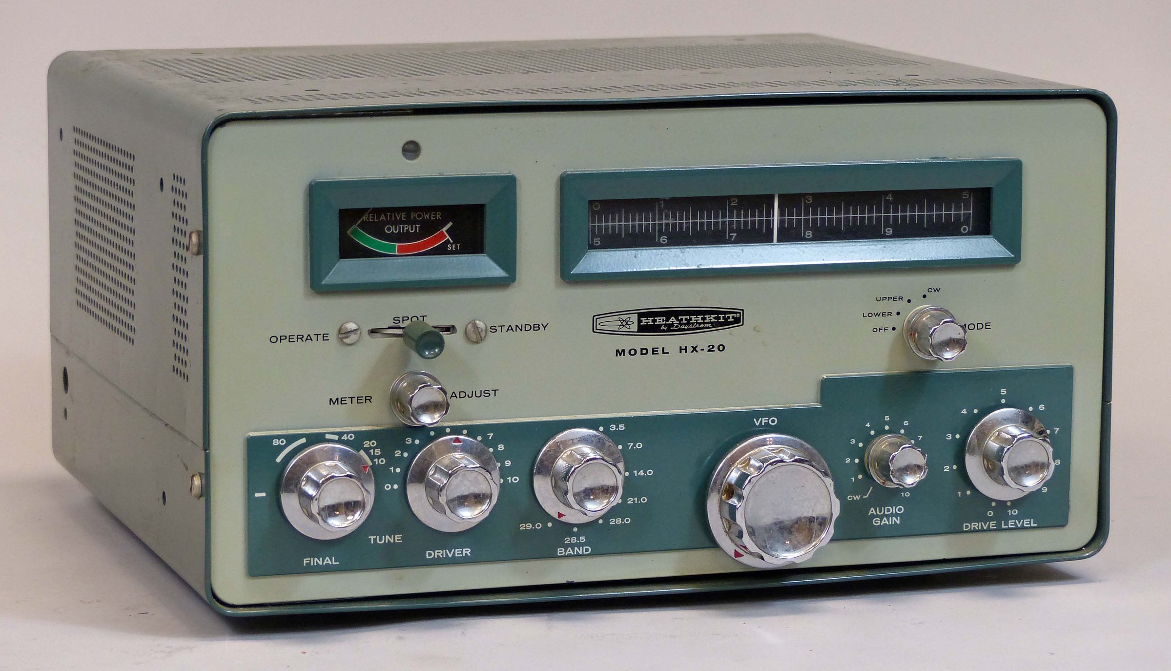
The HX-20 and HR-20 are matching rigs designed primarily for mobile use and represent a general refinement of the MT-1 Cheyenne and the MR-1 Comanche, which they replaced. Indeed, the HX-20 and HR-20 bear a striking resemblance to the MT-1 and MR-1. They are the same size and shape, and use the same color scheme. Even the front panel layout is the same.
The most significant changes are the addition of SSB and VOX, and the elimination of AM, but there are several others. For example, the rotating dial drum of the MT-1 has been replaced with a flat slide rule with just two scales—0 to 500, and 500—1000. (Oddly, the HR-20 receiver retains the rotating dial drum). And the color scheme of the dial and meter is the reversed of its predecessor—white markings on a black background. Finally, the SO-239 RF and Cinch-Jones power connectors of the MT-1 were replaced with an RCA connector and octal plug/sockets on the HX-20.
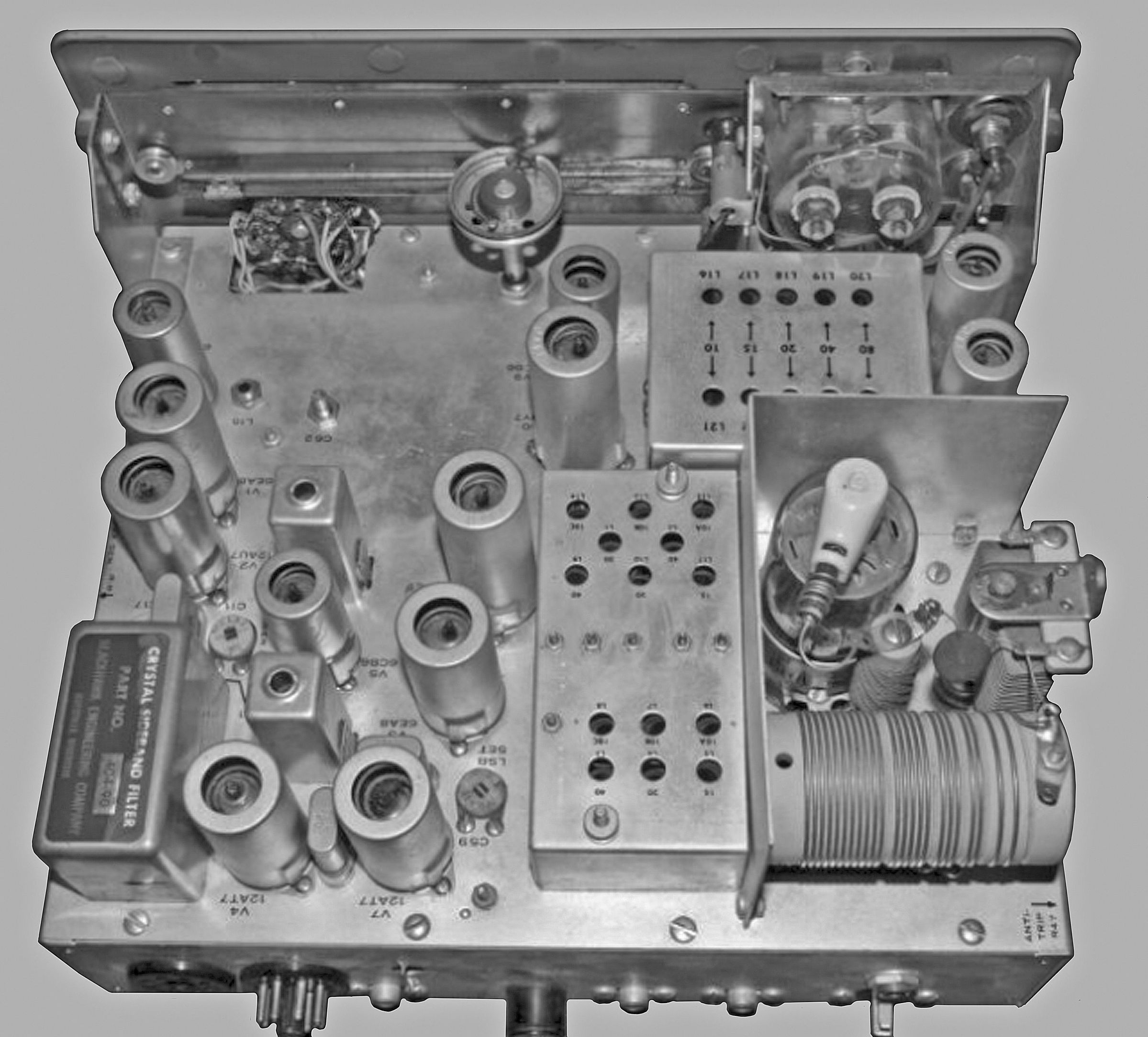
The HX-20 transmitter is a 13 tube design (including a 6146 power amplifier) covering 80 to 15 meters, and three 500 kHz segments of the 10 meter band. No PC boards are used—all wiring is point-to-point. The unit will operate USB, LSB, or CW with an input power of 90 watts PEP, and must be used with one of the following power supplies: the HP-10 or HP-13 series (for mobile use) or the MP-1, HP- 20, or HP-23 series (for 120 VAC use).
Features include crystal filtering and balanced modulator circuits, a temperature compensated VFO, a hermetically sealed bandpass filter, dual conversion heterodyne operation, crystal-controlled oscillators, and ALC. Heath went out of its way to assure the wary shopper of excellent “long term suppression stability” of unwanted carrier and sidebands and touted only 100 Hz drift after warm-up. Advertised carrier suppression is 50 dB below peak output and sideband suppression is 55 dB below peak output.
The HX-20 uses grid block keying and a high impedance microphone (not included).
Front panel controls include operate/spot/standby, mode, final tune, driver tune, band, VFO tune, meter adjust, audio gain, and driver gain. Tune-up is done using the HX-20’s relative power indication.
The final amplifier operates in class AB1 and is designed to work into a 50 to 75Ω load. Unlike the matching HR-20, the HX-20 does not use a rotating dial drum. The tuning mechanism has a 22:1 tuning ratio and is quite a collection of springs and gears—take care when working on it.
Rear panel connections include a power input socket and a loop-through power socket for the receiver, receiver antenna, RF output, key jack, and antenna relay, while the microphone connects on the right side of the chassis. The rear panel also features the fuse, a sideband balance control, and controls for VOX sensitivity and anti-trip. Controls for carrier adjust, carrier null and VOX level are located adjacent to the crystal filter on the right rear corner of the chassis.
The unit is housed in a two-tone green cabinet.
References:
Review. QST. Mar 1964, p. 59.
Review. 73 Amateur Radio. Sep 1963, p. 52.
Nulling carrier. CQ. Dec 1963, p. 60.
Use of 6146B (brief). CQ. May 1965, p. 75.
Improved CW operation. QST. Mar 1966, p. 44.
Improvements. 73 Amateur Radio. Mar 1966, p. 74.
Dial pointer improvement. QST. Jun 1966, p. 74.
Improved carrier suppression. CQ. Oct 1968, p. 48.
Emission types: USB, LSB, CW
Power input: 90 watts PEP SSB
Output impedance: 50 to 75Ω with not more than a 2:1 SWR
Carrier suppression: 50 db below peak output
Unwanted sideband suppression: 55 db below peak output
Frequency coverage (MHz): 3.5 to 4.0, 7.0 to 7.5, 14.0 to 14.5, 21.0 to 21.5, 28.0 to 28.5, 28.5 to 29.0, 29.0 to 29.5
Frequency stability: 500 Hz warmup, 100 Hz after warmup
Keying: grid block of 3rd mixer and driver stages
Audio input: high impedance microphone
Audio frequency response: 400 to 3000 Hz
ALC: applied to IF amplifier stage
Power requirements:
6 volts at 4 amps, or 12 volts at 2.4 amps AC or DC
–125 VDC at 20 mA
300 VDC at 100 mA
600 VDC at 130 mA
Tubes: (1) 0A2, (1) 0C2, (1) 6AU6A, (1) 6AW8A, (2) 6CB6A, (2) 6EA8, (2) 12AT7, (1) 12AU7, (1) 12BY7, (1) 6146B
Photos, general information and specifications from "Heathkit: A Guide to the Amateur Radio Products," by Chuck Penson, WA7ZZE. Used with permission.