Note
The AM-1 was introduced in Fall 1953 and was designed primarily as a companion device for use with the GD-1 series grip dip meters. It is, in fact, built into the same box as the GD-1.
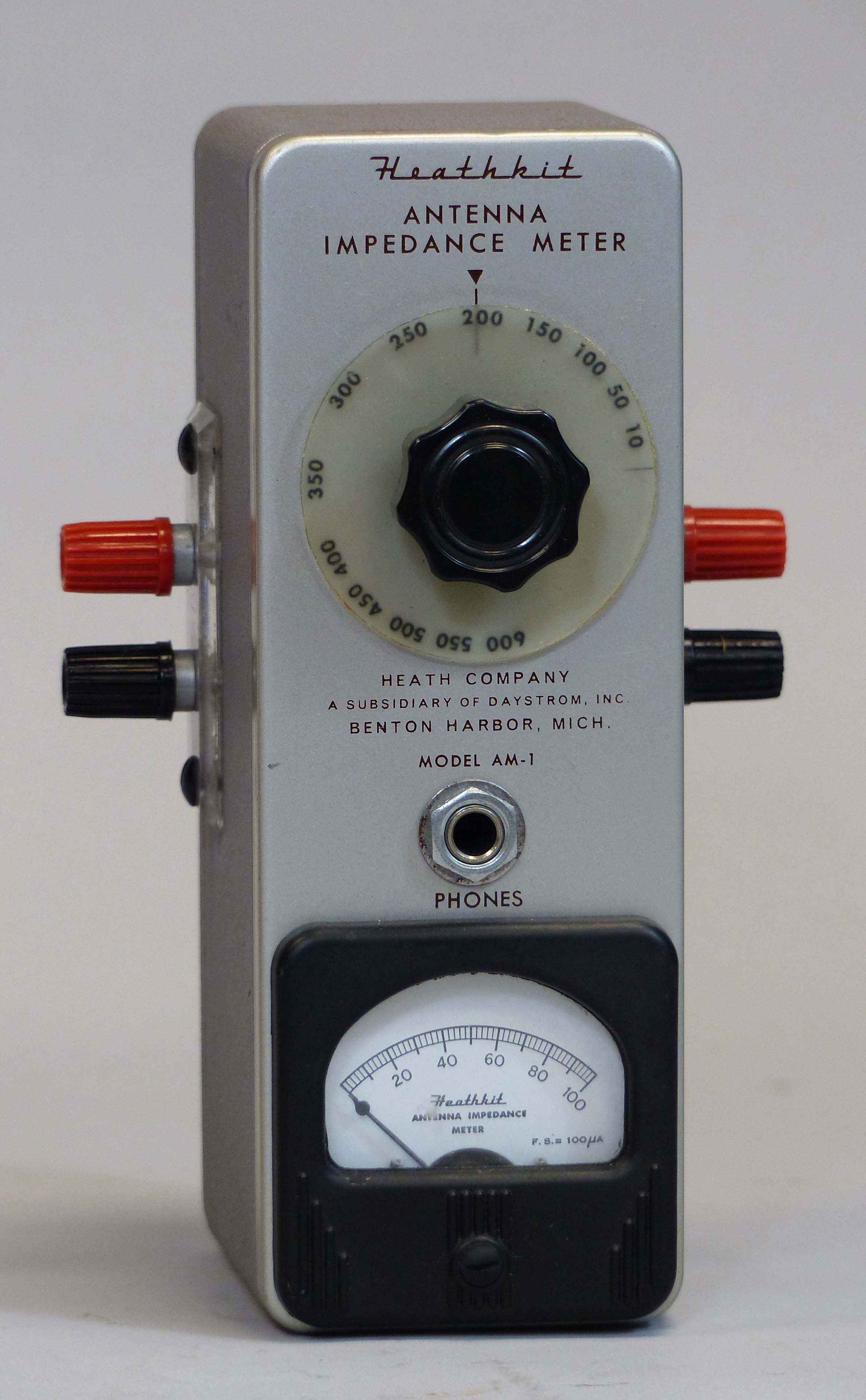
Early units had the impedance calibration numbers screened onto the front panel, and used a pointer knob. By at least 1956 (and perhaps much earlier), this had been replaced with a round knob attached to a circular plastic disk on which the numbers rotated. The paint style matches the GD-1, et al—a silver gray front panel with a gray wrinkle box.
The AM-1 is essentially a resistance type SWR bridge in which one arm of the bridge can be varied. When used with a small RF source (like the GD-1), the AM-1 may be used to determine the impedance and resonant frequency of an antenna, as well as transmission line impedance.
By connecting headphones, the AM-1 also can be used as a monitor for AM transmissions. It also can be used as a field strength meter when high sensitivity is not required. The AM-1 will measure impedance from 0 to 600Ω and has a frequency range from 0 to 150 MHz.
There isn’t much to go wrong with the AM-1—its only active component is a diode. Caution: Do not use the AM-1 with an RF source exceeding a half a watt. Caution: Remove the bottom cover first to avoid damage to the front panel when opening the unit for inspection.
The small assembly manual for the AM-1 contains detailed instructions for use of the unit in a wide variety of applications and would be useful to have.
References:
Review. CQ. Feb 1954, p. 52.
Frequency range: 0-150 MHz
Impedance range: 0-600Ω
Null indicator: 100 µA meter
Photos, general information and specifications from "Heathkit: A Guide to the Amateur Radio Products," by Chuck Penson, WA7ZZE. Used with permission.