Note
HW-104 1975-1977 $539.95
HW-104A 1977-1977 $489.95
Released for Christmas in 1975, the HW-104 (there was no HW-102 or HW-103) was the lower cost alternative to the SB-104, which had been released a year earlier.
As with the HW-101 and SB-101, the HW-104 is almost identical to the SB-104. The basic design and electronics are the same. Both are fully solid state units, including the final amplifier. The main difference was the frequency display. The SB-104 uses an expensive and complicated digital display and attendant high voltage converter. The HW-104 uses a much simpler analog dial. And because the HW-104 was released about a year after the SB-104, many of the problems suffered by the SB-104 had been worked out by the time the HW-104 was released.
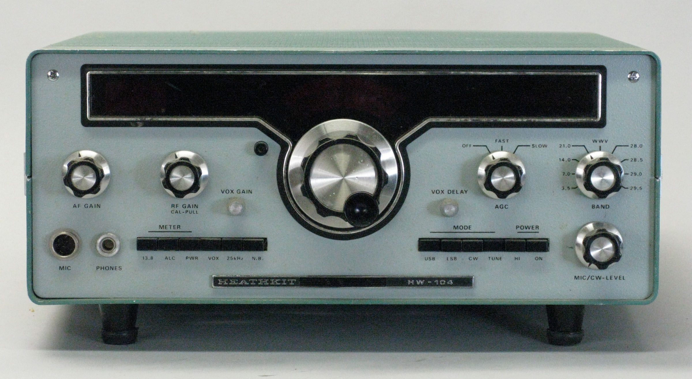
Front panel controls include pushbutton selection of meter function, power off/on, VOX, 25 kHz calibrator, and optional noise blanker. Pushbuttons also select operating mode and power level. Other front panel controls include AF and RF gain (pull for 100 kHz calibrator), main tuning, AGC speed, band, mic/CW level, VOX gain, and VOX delay.
T/R switching is accomplished with a mechanical relay, so true QSK is not possible.
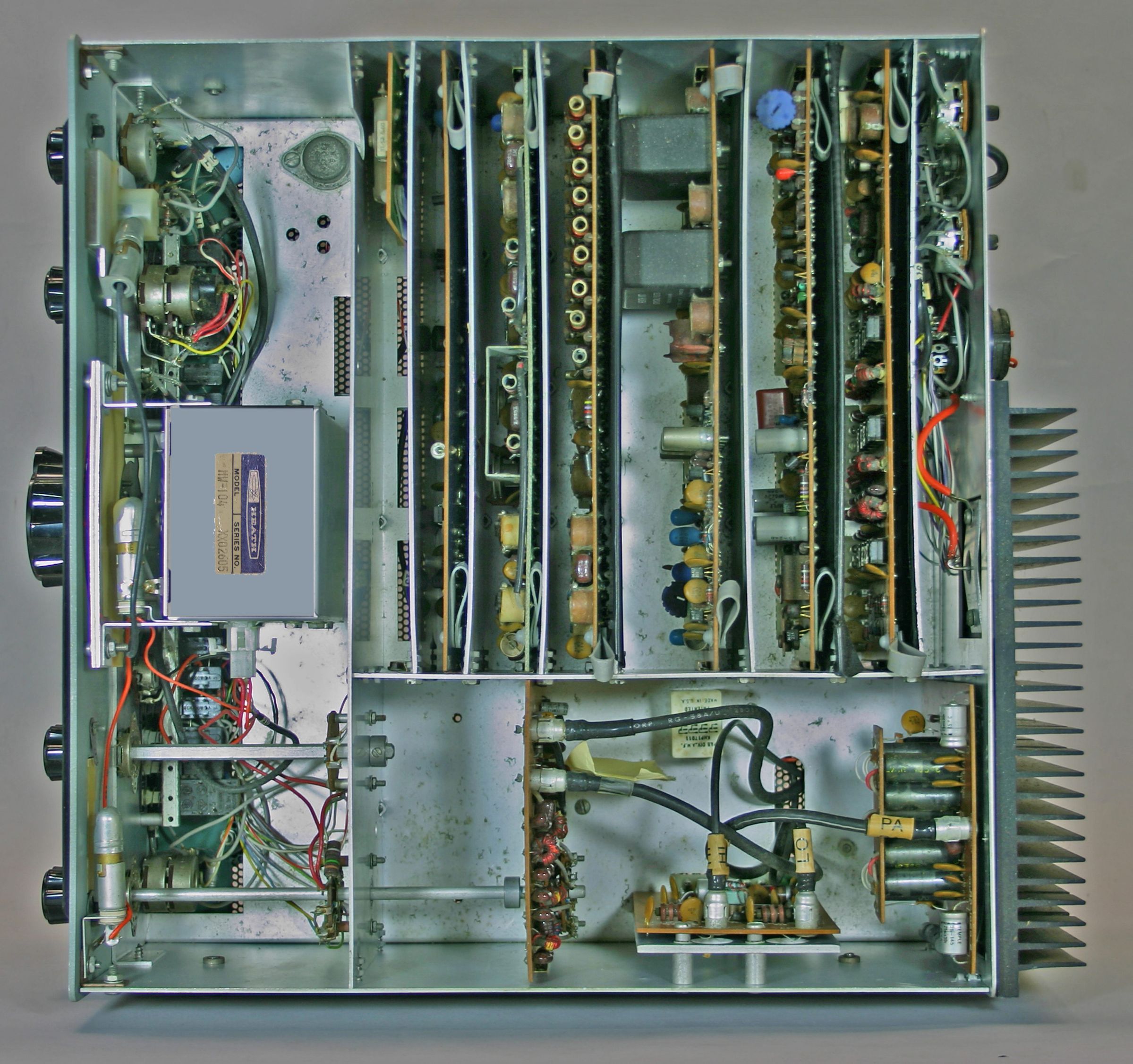
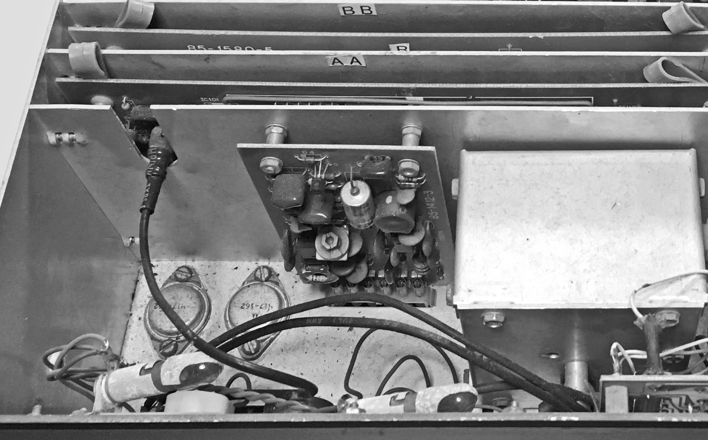
The HW-104 is built with 15 printed circuit boards, 11 of which are plug-in circuit cards. There is no “motherboard.” The cards plug into sockets on the chassis which are connected by two wiring harnesses on the underside. As a cost-saving measure, Heath used less expensive phenolic material for the circuit boards instead the more expensive epoxy boards used in the SB-104. Since the circuit boards interchangeable, it may be possible to find HW-104s with one or more epoxy boards. The two types are readily identifiable by their color. The phenolic boards are reddish brown, while the epoxy boards are green.
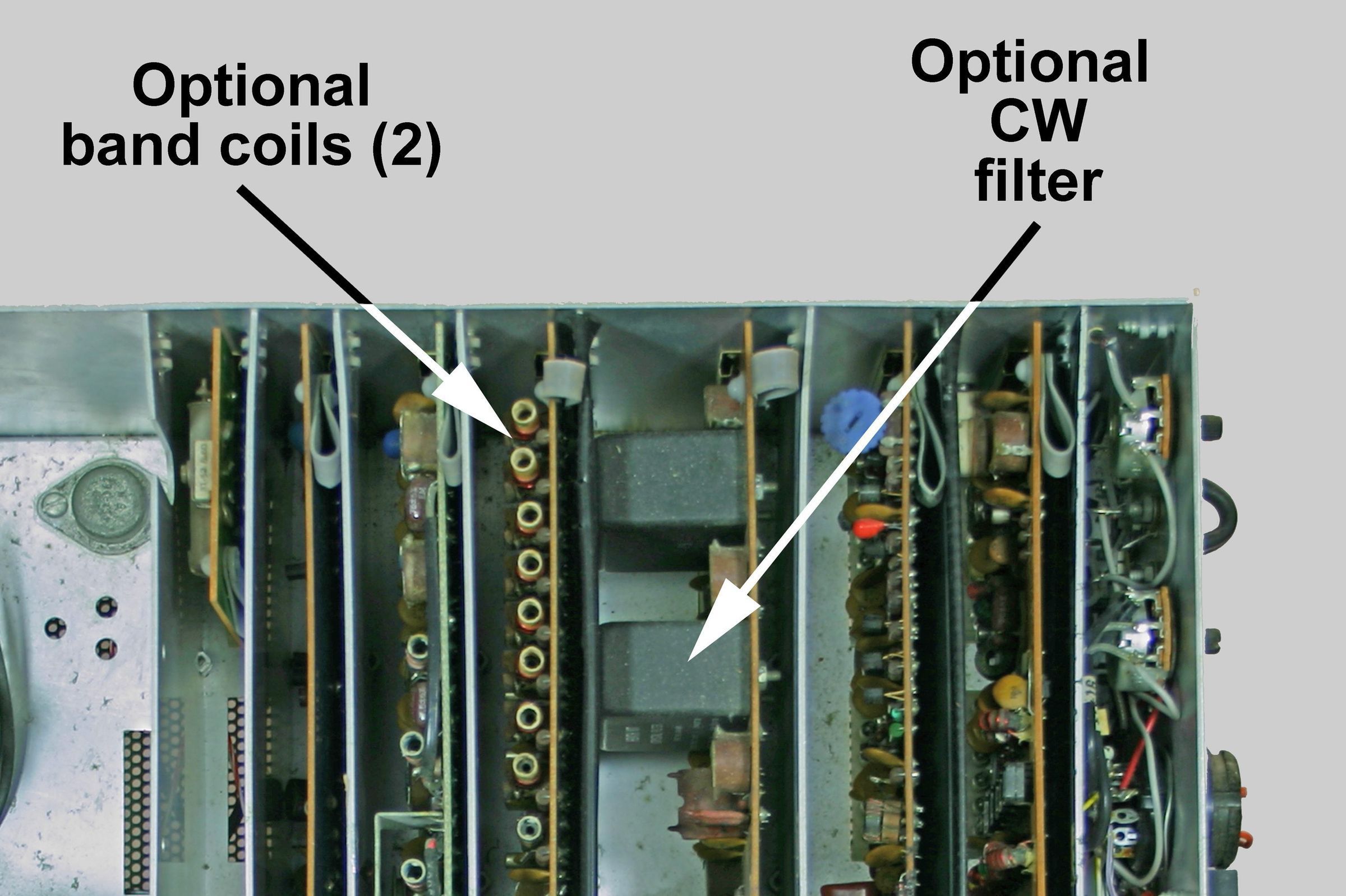
The basic specifications of the two units are also very similar. Frequency coverage is 80 through 10 meters (up to 29.0 MHz). Coverage to 29.7 MHz was provided with an optional accessory (a set of two coils and two crystals mounted on a space provided on the front end of a PC board). Refer to photo for the location of the optional band components.
WWV reception on 15 MHz is also provided but there are no provisions for WARC coverage.
Rear panel controls include sidetone level, anti-VOX, and a switch to select separate or common antenna connections.
Rear panel connections include RCA jacks for the following: phone patch in and out, aux audio, key, 4-8Ω speaker (there is no internal speaker), VFO in and out, ALC, driver output, IF output, receiver antenna, common antenna, and two spares. Note: For normal operation there must be a jumper cable between the VFO “in” and “out” jacks. There are also two 11-pin connectors—a plug for 12 VDC power input and an accessory jack for use with the SB-644 external VFO. For normal operation there must be a jumper wire between pins 2 and 5 of the accessory socket.
The receiver is a broadband design with a 4-pole crystal filter, sensitivity of better than 1.0 µV, and selectivity of 2.1 kHz at 6 db down. An optional CW filter provides selectivity of 400 Hz at 6 dB down. The top cover must be removed to check for the presence of the CW filter and extended 10-meter coverage. .
An optional noise blanker was available (SBA-104-1). It is a small, plug-in circuit board. If present, it is located on the left side of the transceiver, just behind the front panel, adjacent to the VFO. Refer to photo for the location of the noise blanker. Note: The noise blanker front panel pushbutton is present whether or not the noise blanker itself is installed.
Drift is less than 100 Hz per hour after 30 minutes warmup. Transmitter output power for both SSB and CW is 100 watts (PEP SSB) in high power mode and 1 watt in low power mode.
The main feature of the HW-104 is, of course, the broadband design, which facilitates instant band changing and eliminates the need to tune up, and although a “tune” mode is provided, it is intended primarily for the adjustment of antenna tuners.
Behind the red plastic window is the illuminated VFO dial, a meter reading S-units, relative power, ALC and 13.8 VDC, and an illuminated window for display of your callsign. (The clever person will figure out some way to change or eliminate the callsign).
The HW-104A was introduced in the Christmas 1977 catalog and discontinued almost immediately. It is not clear if any were actually sold, as the unit did not appear in any subsequent catalogs. As of this writing, a Google search for “Heathkit HW-104A” returned zero hits. The difference between the 104 and 104A was a redesigned and pre-assembled front-end board (board G) that significantly improved receiver sensitivity from 1.0 µV to 0.5 µV. Bear in mind that the sensitivity of the HW-101 was 0.3 µV.
Note: The card edge connectors used in the HW-104 almost certainly will develop oxidation over time leading to erratic operation. These connectors should be thoroughly cleaned.
Warning: DC input voltage must NOT EXCEED 16 volts or damage will result.
Warning: reverse polarity will also result in damage as the HW-104 is not polarity protected.
For power supply connections see HP-1144(A).
The two-tone green cabinet matches other HW series units.
References:
Review. QST. Dec 1976, p. 37.
Modification of PC board etching pattern. QST. Jan 1980, p. 54.
RIT for. 73 Amateur Radio. Apr 1979, p. 128.
RIT for. QST. Jan 1980, p.16.
RIT for. QST. Mar 1980, p. 49.
TRANSMITTER
RF power output (50Ω nonreactive load):
high power: SSB,100 PEP ±1 db; CW, 100 watts ±1 db
low power: SSB, 1 watt PEP minimum; CW, 1-watt minimum
Output impedance: 50Ω, less than 2:1 SWR
Carrier suppression: 55 db down from 100 watt single-tone output at 1000 Hz
Unwanted sideband suppression: 55 db down from 100 watt single-tone output at 1000 Hz
Harmonic radiation: 45 db below 100 watt output
Spurious radiation: –50 db within ±3 MHz of carrier, except on 3.5 MHz band, –40 db at 3.395 MHz
Third order distortion: 30 db down from two-tone output at 100 watts
Sidetone: about 700 Hz
Mic input: high impedance with a rating if –45 to –55 db; approximately 25kΩ.
RECEIVER
Sensitivity: less than 1.0 µV for 10 db signal plus-noise-to-noise ratio
Selectivity:
SSB: 2.1 kHz minimum at 6 db down, 5 kHz maximum at 60 db down (2:1 nominal shape factor)
CW (filter optional): 400 Hz at 6 db down, 2 kHz at 60 db down
Overall gain: less than 1.0 µV for 0.5 watts audio output
Audio output: 2.5 watts into 4Ω, 1.25 watts into 8Ω, at less than 10% THD
Headphones: low impedance (4 to 8Ω)
AGC: less than 1.0 millisecond attack time, switch selectable release time of 100 milliseconds, 1 second, and OFF
Intermodulation distortion: –60 db
Image rejection: –60 db
IF rejection: –60 db
Internally generated spurs: below 2.0 µV equivalent, except at 3.65, 3.74, 14.24, 21.2 MHz
GENERAL
Frequency coverage (MHz): 3.5 to 4.0, 7.0 to 7.3, 14.0 to 14.5, 21.0 to 21.5, 28.0 to 29.0. Optional coverage to 29.7. (15.0 to 15. 3 receive only)
Frequency stability: less than 100 Hz/30 min. drift after 30 min. warmup, less than 100 Hz drift for ±10% change in line voltage
Modes: USB, LSB, CW
Dial accuracy: within 2.5 kHz after calibration to nearest 100 kHz marker
Calibrator: 25 kHz and 100 kHz markers
Tuning rate: approximately 15 kHz per revolution
Backlash: 50 Hz or less
Audio frequency response: 350 to 2450 Hz ±75 Hz (6 db bandwidth)
Tuning backlash: 100 Hz
Phone patch impedance: 4Ω output to speaker; high impedance output to transmitter
Power requirements:
13.8 VDC nominal (16 VDC maximum)
receive: 1.5 amps
transmit, high: 20 amps
transmit, low: 2.5 amps
Photos, general information and specifications from "Heathkit: A Guide to the Amateur Radio Products," by Chuck Penson, WA7ZZE. Used with permission.