Note
The basic specifications for the “A” series Single-Banders are the same as for the originals. Most of the changes are related to operating convenience. Refer to HW-12 and HW-12A for a discussion of basic features.
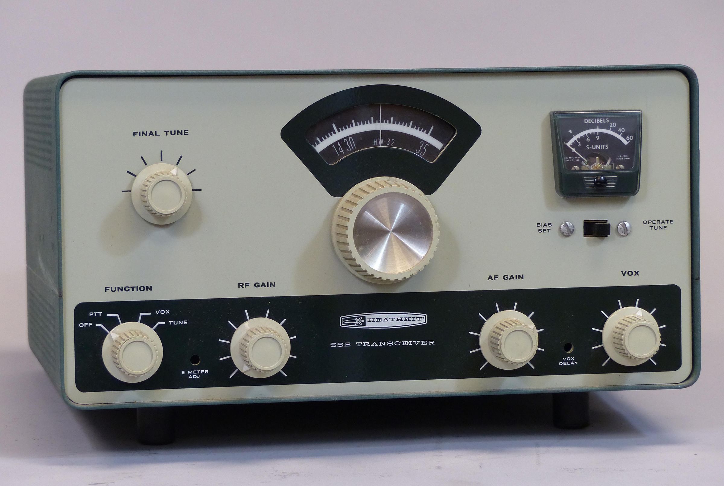
Frequency coverage for the HW-32 is 14.2 to 14.35 MHz. It operates only in USB. Caution: Operate on 250 VDC only.
See HW-12 for addition discussion.
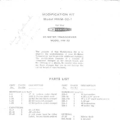
HWM-32-1 MODIFICATION
When the HW-32A was introduced late in 1966, Heath released a modification to incorporate some of the 32A’s improvements in the HW-32. The mod was designed to improve neutralization and provide additional stability. The modification involved significant board-level and other changes, and added a shield for the final amplifier. Installing the shield required drilling holes in the chassis. This is not a modification for the faint of heart.
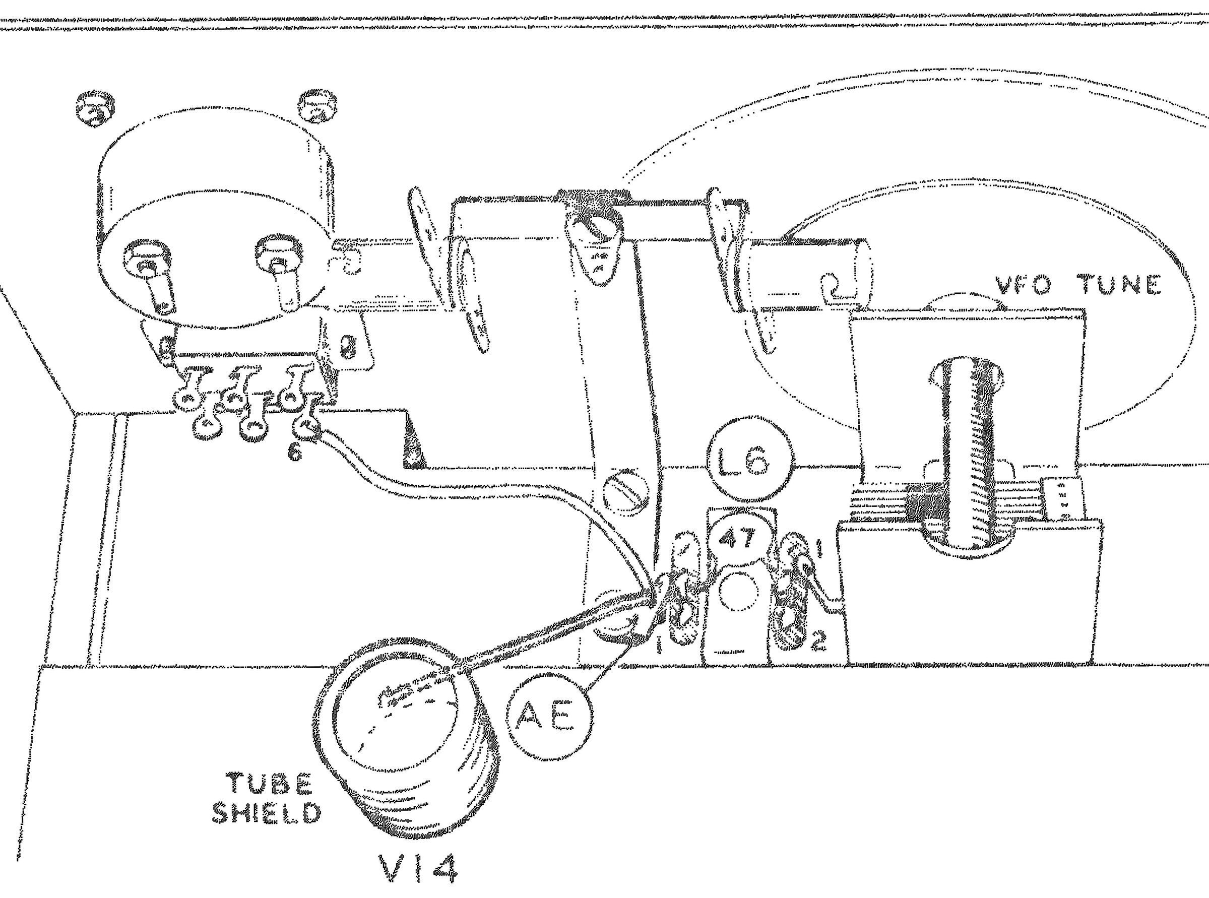
The presence of the modification can be detected by looking for the metal shielding box over the final amplifier tubes. If the customer chose not to accomplished this piece of the mod, look for a tube shield installed on V14. Additionally, a wire soldered to this tube shield was attached to a nearby solder lug. Refer to illustration.
References:
Review. QST. Jan 1964, p. 48.
Modifications. QST. Apr 1965, p. 71.
Modifications (more on). QST. May 1965, p. 59.
Modification to final. CQ. Dec 1965, p. 75.
Q Multiplier for. CQ. Dec 1965, p. 75.
Adding bands (reference only). CQ. Jan 1966, p. 70.
Power supply for. CQ. Mar 1966, p. 48.
Alignment tip. QST. May 1966, p. 74.
CW modification. CQ. Feb 1967, p. 36.
Dial modification. QST. Jun 1968, p. 36.
Noise limiter. Ham Radio. Mar 1971, p. 67.
CW coverage with. CQ. Jul 1971, p. 18.
A receiver pre-amp for. CQ. Mar 1976, p. 26.
VFO slippage and backlash. QST. Sep 1976, p. 39.
Use as QRP. QST. Sep 1977, p. 45.
Receiver Section
Frequency coverage: 14.2 to 14.35 MHz
Receiver mode: lower sideband only
Sensitivity: 1.0 µV input will provide at least 15 db signal plus noise to noise ratio
Selectivity: 2.7 kHz @ 6 db, 6 kHz @ 50 db
IF: 2305 kHz
Image rejection: 60 db
IF rejection: 65 db
Receiver audio response: 400 to 3000 Hz
Receiver audio power output: 1 watt
External speaker impedance: 8Ω
Antenna input impedance: 50Ω nominal, unbalanced
Transmitter section
Frequency coverage: 14.2 to 14.35 MHz
Stability: less than 200 Hz per hour after one hour warmup
RF power output: 200 watts PEP
Unwanted sideband suppression: 45 db minimum below peak output @ 1000 Hz
Carrier suppression: 45 db minimum below peak output
Output impedance: 50Ω nominal, unbalanced
Transmitter audio response: 400 to 3100 Hz
Microphone required: hi-Z crystal, ceramic or dynamic; 10 mV minimum output
Power requirements:
800 VDC at 250 mA
250 VDC at 100 mA
–125 VDC at 5 mA
12 volts AC or DC at 3.75 ampsHW
Tubes: (3) 6EA8, (5) 6AU6, (1) 6BE6, (1) 12AT7, (1) 12BY7, (1) 6EB8,
(2), 6GE5
Photos, general information and specifications from "Heathkit: A Guide to the Amateur Radio Products," by Chuck Penson, WA7ZZE. Used with permission.