Note
The SB-500 is designed to permit two-meter SSB or CW operation using Heath SB or HW series HF transceivers.
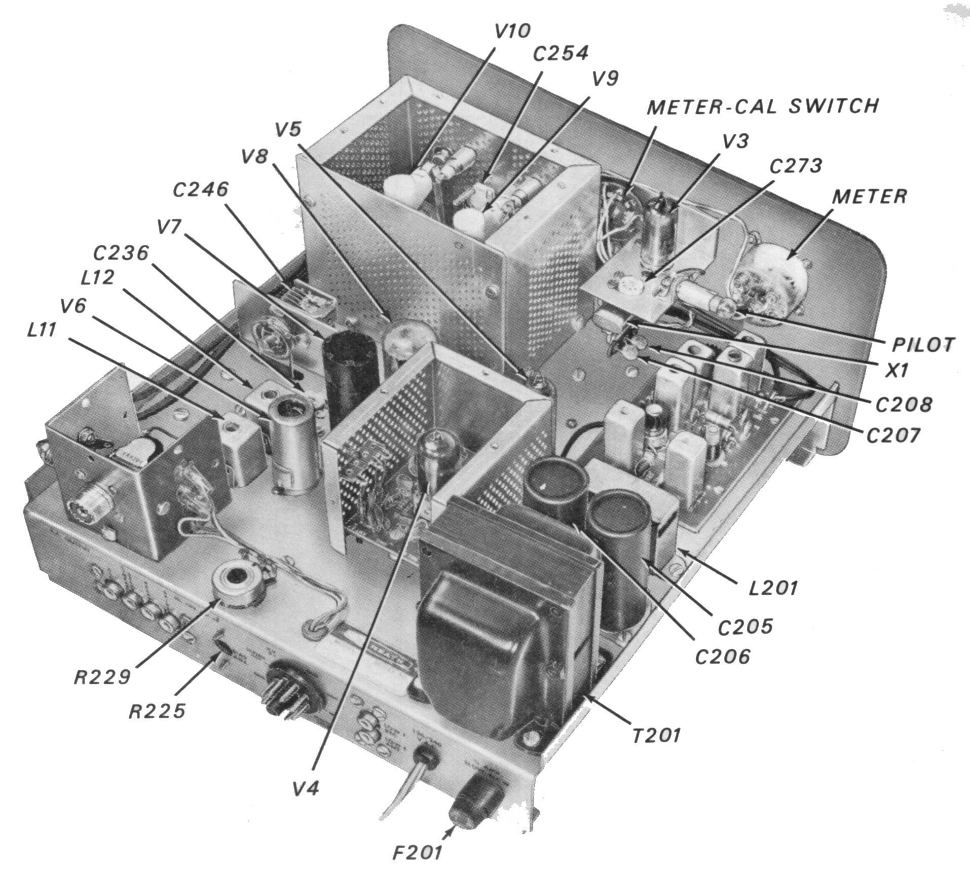
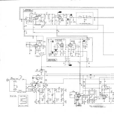
The SB-500 is designed around 10 tubes including a pair of 6DS4 Nuvistors and a pair of 6146 final amplifiers operating in class AB1. Only two small PC boards are used, the bulk of the wiring is point to point.
The SB-500 can be wired to down convert to the 10-meter or six-meter bands—the choice is made during assembly. The receiver section sensitivity is 0.2 µV for 10 dB signal plus noise-to-noise ratio. The transmitter section will deliver about 140 watts PEP SSB and about 50 watts CW to a 50Ω antenna with an SWR of less than 2:1. The transmitter duty cycle is 50 percent.
A regulated 150 volt supply powers the RF amplifier/mixer, heterodyne oscillator and crystal calibrator. The front panel meter reads plate current and relative power. The meter itself is the same one used with the SB-400/401.
FREQUENCY WIRING OPTIONS
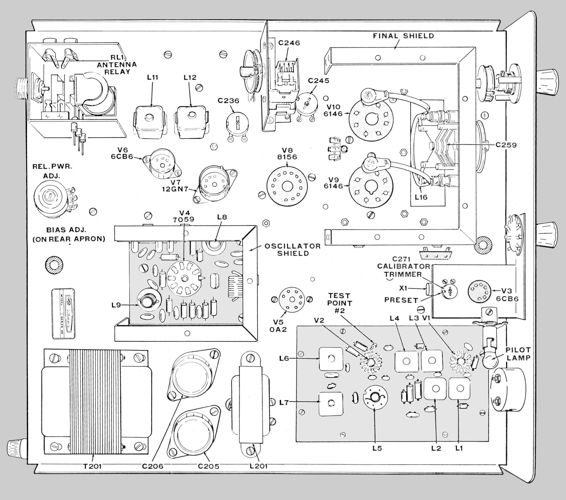
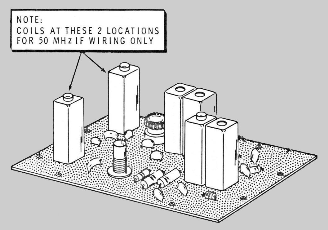
The frequency range of the SB-500 is any 2 MHz segment from 144 to 148 MHz translated to 50-54 MHz or 28-32 MHz. Determining which frequency option was chosen is simple. Refer to illustrations. Locate the receiver PC board at the left front corner of the unit. On the end of the PC board farthest from the front panel there is space for two metal can-type coils (L6 and L7). If the cans are present, the unit has been wired for operation with the SB-110 and 110A six-meter transceiver. If the cans are not in place, the unit has been wired for operation on the 10-meter band with the SB-101 or 102, the HW-100 or 101, or the SB-301/401 combination.
SB and HW SERIES MODIFICATIONS
The SB-500 is plug-and-play compatible with the SB-102 or HW-101. The SB-500 assembly manual contains specific modification instructions for the SB-110, SB-101, and HW-100 transceivers, as well as the SB-301/401. Use with other makes of radios is also possible for the more technically inclined operator. Alignment requires your HF station, a dummy load, and a VTVM.
Caution: While the SB-500 is connected to your HF station, a full 800 volts is applied to the 500’s final tubes even when the SB-500 is off.
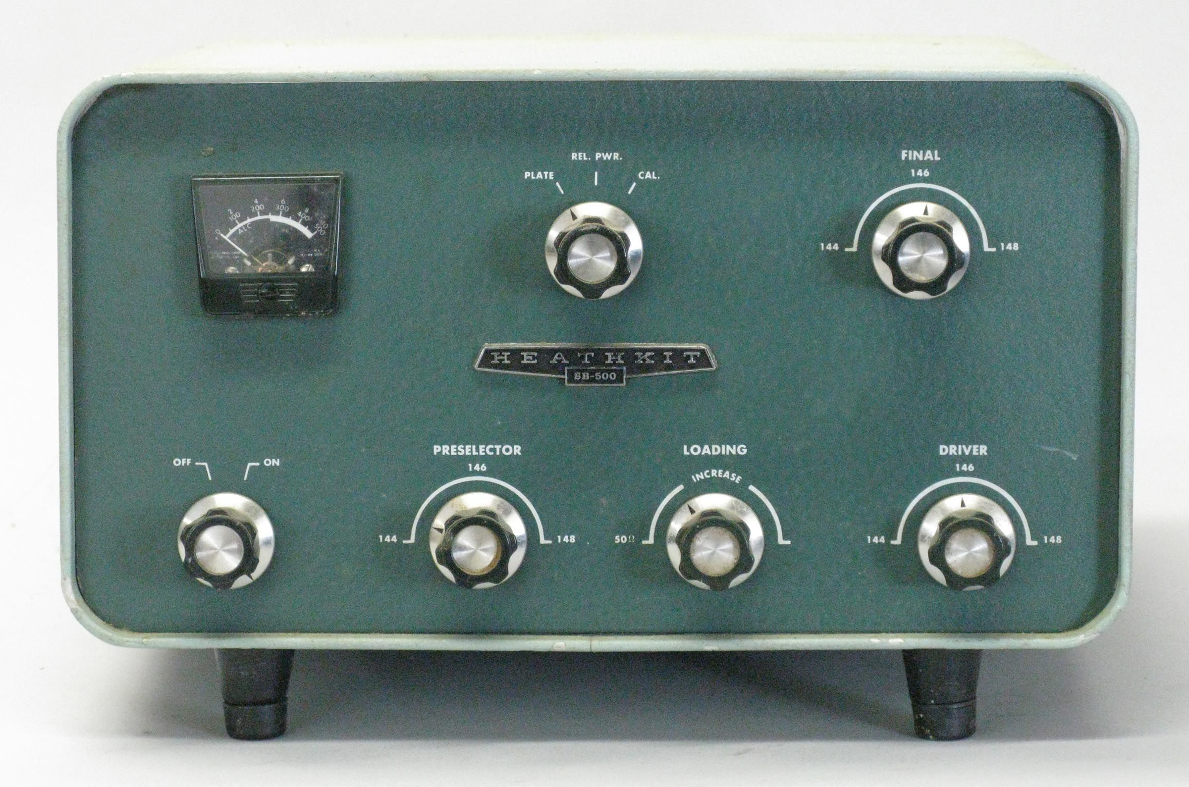
Front panel controls include meter function/calibrate switch, final tuning, on/off function, preselector, final loading, and driver tuning. Internal controls include relative power adjust and bias adjust. An illuminated front panel meter reads plate current or relative power.
Rear panel connections include RCA jacks for RF output, ALC, linear relay, drive, bias adjust, low frequency receiver output, and low frequency RF input. A relative power adjustment control is located on the rear deck. There is also an octal power plug to pick up some voltages and signals not provided by the SB-500’s built-in supply.
The SB-500 is built into the same size cabinet as the SB-303 and 313 and is finished in the standard SB two-tone green wrinkle paint.
Having the manual is essential.
References:
Review. QST. Sep 1970, p. 43.
Review. CQ. Sep 1969, p. 59.
RECEIVER SECTION
Sensitivity: 0.2 µV for 10 db signal-to-noise plus noise for SSB
Spurious response: all below 0.1 µV equivalent, except at 143.39 (50 MHz IF only)
Antenna input: 50Ω unbalanced
Crystal calibrator: 1 MHz
TRANSMITTER SECTION
DC power input: 140 watts PEP
RF power output: 50 watts (50% duty cycle)
Output impedance: 50Ω with less than 2:1 SWR
Exciter power: as little as 0.5 watts
GENERAL
Frequency range: 44 to 148 MHz translated to 50-54 MHz or 28-32 MHz (any 2 MHz segment)
Modes: USB, LSB, CW
Power requirements:
120/240 VAC, 50/60 Hz, 82 watts
700 to 800 VDC at 200 mA (from driving unit)
Size: 12.25 wide x 6.75 high x 14 deep; Weight: 14.5 lbs
Tubes: (1) 0A2, (2) 6CB6, (2) 6DS4, (1) 12GN7, (1) 7059,
(1) 8156, (2) 6146*
*6146A or 6146B may be directly substituted
Photos, general information and specifications from "Heathkit: A Guide to the Amateur Radio Products," by Chuck Penson, WA7ZZE. Used with permission.